STC.{D,W} – Store Coprocessor
Description
Stores the source register value to the location specified by the addressing mode.
Operation:
I. *(Rp + (ZE(disp8) \ll 2)) \leftarrow CP#(CRd+1:CRd); II. *(Rp) \leftarrow CP#(CRd+1:CRd); Rp \leftarrow Rp+8; III. *(Rb + (Ri \ll sa2)) \leftarrow CP#(CRd+1:CRd); IV. *(Rp + (ZE(disp8) \ll 2)) \leftarrow CP#(CRd); V. *(Rp) \leftarrow CP#(CRd); Rp \leftarrow Rp+4; VI. *(Rb + (Ri \ll sa2)) \leftarrow CP#(CRd);
Syntax:
I. stc.d CP#, Rp[disp], CRs II. stc.d CP#, Rp++, CRs III. stc.d CP#, Rb[Ri<<sa], CRs IV. stc.w CP#, Rp[disp], CRs V. stc.w CP#, Rp++, CRs VI. stc.w CP#, Rb[Ri<<sa], CRs
Operands:
I-VI. # \in \0, 1, ..., 7
I-II, IV-V.s \in \0, 1, ..., 15
I-III. s \in \0, 2, ..., 14
I, IV. disp \in \0, 4, ..., 1020
III, VI. {b, i} \in \0, 1, ..., 15
III, VI. sa \in \0, 1, 2, 3\
Status Flags:
Q: Not affected V: Not affected N: Not affected Z: Not affected C: Not affected
Opcode:
344 AVR32 32000D–04/2011
AVR32
Format I:
 Format II:
Format III:
Format IV:
Format V:
Format VI:
Example: stc.d CP2, R2[0], CR0
32000D–04/2011 345
STC0.{D,W} – Store Coprocessor 0 Register
Description Stores the coprocessor 0 source register value to the location specified by the addressing mode.
Operation: I. (Rp + (ZE(disp12) << 2)) ← CP#(CRd+1:CRd); II. (Rp + (ZE(disp12) << 2)) ← CP#(CRd);
Syntax: I. stc0.d Rp[disp], CRs II. stc0.w Rp[disp], CRs
Operands: I-II. p ∈ {0, 1, ..., 15} I. s ∈ {0, 2, ..., 14} II. s ∈ {0, 1, ..., 15} I, IV. disp ∈ {0, 4, ..., 16380}
Status Flags: Q: Not affected V: Not affected N: Not affected Z: Not affected C: Not affected
Opcode:
Format I:
 31 29 28 25 24 20 19 16
| 1 | 1 | 1 | 1 | 0 | 1 | 1 | 1 | 1 | 1 | 0 | 1 | 0 | Rp |
15 12 11 8 7 0
| disp[11:8] | CRs[3:1] | 0 | disp[7:0] |
Format II:
31 29 28 25 24 20 19 16 | 1 | 1 | 1 | 1 | 0 | 1 | 0 | 1 | 1 | 0 | 1 | 0 | Rp | 15 12 11 8 7 0 | disp[11:8] | CRs | disp[7:0] |
Example: stc0.d R2[0], CR0
346 AVR32 32000D–04/2011
AVR32
STCM.{D,W} – Store Coprocessor Multiple Registers
Description Writes multiple registers in the addressed coprocessor into the specified memory locations.
Operation:
I. Storeaddress \leftarrowRp; if Opcode[--] == 1 then for (i = 0 to 7) if ReglistCPD8[i] == 1 then *(--Storeaddress) \leftarrowCP#(CR(2*i)); *(--Storeaddress) \leftarrowCP#(CR(2*i+1)); Rp \leftarrow Storeaddress; else for (i = 7 to 0) if ReglistCPD8[i] == 1 then *(Storeaddress++) \leftarrowCP#(CR(2*i+1)); *(Storeaddress++) \leftarrowCP#(CR(2*i));
II Storeaddress \leftarrowRp; if Opcode[--] == 1 then for (i = 0 to 7) if ReglistCPH8[i] == 1 then *(--Storeaddress) \leftarrowCP#(CRi+8); Rp \leftarrow Storeaddress; else for (i = 7 to 0) if ReglistCPH8[i] == 1 then *(Storeaddress++) \leftarrowCP#(CRi+8);
III Storeaddress \leftarrowRp; if Opcode[--] == 1 then for (i = 0 to 7) if ReglistCPL8[i] == 1 then *(--Storeaddress) \leftarrowCP#(CRi); Rp \leftarrow Storeaddress; else for (i = 7 to 0) if ReglistCPL8[i] == 1 then *(Storeaddress++) \leftarrowCP#(CRi);
32000D–04/2011 ATMEL® 347
Syntax:
I. stcm.d CP#, {--}Rp, ReglistCPD8 II. stcm.w CP#, {--}Rp, ReglistCPH8 III. stcm.w CP#, {--}Rp, ReglistCPL8
Operands:
I-III. # ∈ {0, 1, ..., 7} p ∈ {0, 1, ..., 15}
I. ReglistCPD8 ∈ {CR0-CR1,CR2-CR3,CR4-CR5,CR6-CR7,CR8-CR9, CR10-CR11,CR12-CR13,CR14-CR15}
II. ReglistCPH8 ∈ {CR8, CR9, CR10, ..., CR15}
III. ReglistCPL8 ∈ {CR0, CR1, CR2, ..., CR7}
Status Flags:
Q: Not affected. V: Not affected. N: Not affected. Z: Not affected. C: Not affected.
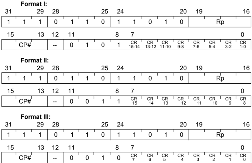
Opcode:
Format I:
31 29 28 25 24 20 19 16 1 1 1 0 1 1 0 1 1 0 1 0 Rp 15 13 12 11 8 7 0 CP# -- 0 1 0 1 CR15-14 CR13-12 CR11-10 CR9-8 CR7-6 CR5-4 CR3-2 CR1-0
Format II:
31 29 28 25 24 20 19 16 1 1 1 0 1 1 0 1 1 0 1 0 Rp 15 13 12 11 8 7 0 CP# -- 0 0 1 1 CR15 CR14 CR13 CR12 CR11 CR10 CR9 CR8
Format III:
31 29 28 25 24 20 19 16 1 1 1 0 1 1 0 1 1 0 1 0 Rp 15 13 12 11 8 7 0 CP# -- 0 0 1 0 CR7 CR6 CR5 CR4 CR3 CR2 CR1 CR0
Example:
stcm.w CP2, --SP, CR2-CR5
Note:
Emtpy ReglistCPH8/ReglistCPL8/ReglistCPD8 gives UNDEFINED result.
STCOND – Store Word Conditionally
Description The source register is stored to the word memory location referred to by the pointer address if SREG[L] is set. Also, SREG[L] is copied to SREG[Z] to indicate a success or failure of the operation. This instruction is used for atomical memory access.
Operation: I. SREG[Z] ← SREG[L]; If SREG[L] *(Rp + SE(disp16)) ← Rs;
Syntax: I. stcond Rp[disp], Rs
Operands: I. {s , p} ∈ {0, 1, ..., 15} disp ∈ {-32768, -32767, ..., 32767}
Status Flags: Q: Not affected. V: Not affected. N: Not affected. Z: SREG[Z] ← SREG[L]. C: Not affected.
Opcode:

Note:
32000D–04/2011 349
ATML
STDSP – Store Stack-Pointer Relative
Description Stores the source register value to the memory location referred to specified by the Stack Pointer and the displacement.
Operation: I. *( (SP && 0xFFFF_FFFC) + (ZE(disp7) << 2) ) ← Rs;
Syntax: I. stdsp SP[disp], Rs
Operands: I. disp ∈ {0, 4, ..., 508} s ∈ {0, 1, ..., 15}
Status Flags: Q: Not affected V: Not affected N: Not affected Z: Not affected C: Not affected
Opcode:
\begin{tabular}{|c|c|c|c|c|c|c|c|c|c|c|c|c|c|c|c|} \hline \multicolumn{3}{|c|}{15 \quad 13} & \multicolumn{2}{|c|}{12 \quad 11} & \multicolumn{7}{|c|}{10 \quad \quad \quad \quad \quad \quad \quad \quad \quad \quad \quad \quad \quad \quad \quad 4} & \multicolumn{2}{|c|}{3 \quad \quad \quad \quad \quad \quad \quad \quad \quad \quad \quad \quad \quad \quad \quad 0} \ \hline 0 & 1 & 0 & 1 & 0 & \multicolumn{7}{|c|}{disp7} & \multicolumn{2}{|c|}{Rs} \ \hline \end{tabular}
350 AVR32 32000D–04/2011
AVR32
STHH.W – Store Halfwords into Word
Description The selected halfwords of the source registers are combined and stored to the word memory location referred to by the pointer address.
Operation: If (Rx-part == t) then high-part = Rx[31:16] else high-part = Rx[15:0]; If (Ry-part == t) then low-part = Ry[31:16] else low-part = Ry[15:0];
I. (Rp + ZE(displ << 2)) ← {high-part, low-part}; II. (Rb + (Ri << sa2)) ← {high-part, low-part};
Syntax: I. sthh.w Rp[disp], Rx:, Ry: II. sthh.w Rb[Ri << sa], Rx:, Ry:
Operands: I. {p, x, y} ∈ {0, 1, ..., 15} disp ∈ {0, 4, ..., 1020} part ∈ {b,t} II. {b, i, x, y} ∈ {0, 1, ..., 15} sa ∈ {0, 1, 2, 3} part ∈ {b,t}
Status Flags: Q: Not affected. V: Not affected. N: Not affected. Z: Not affected. C: Not affected.
Opcode: Format I:

32000D-04/2011 ATMEL 351
Format II:
352 AVR32 32000D–04/2011
STM – Store Multiple Registers
Description
Stores the registers specified to the consecutive memory locations pointed to by Rp. Both registers in the register file and some of the special-purpose registers can be stored.
I. Storeaddress \leftarrow Rp; if Opcode[--] == 1 then for (i = 0 to 15) if Reglist16[i] == 1 then *(--Storeaddress) \leftarrow Ri; Rp \leftarrow Storeaddress; else for (i = 15 to 0) if Reglist16[i] == 1 then *(Storeaddress++) \leftarrow Ri;
Syntax: I. stm {--}Rp, Reglist16
Operands: I. Reglist16 \in {R0, R1, R2, ..., R12, LR, SP, PC} p \in {0, 1, ..., 15}
Status Flags: Q: Not affected. V: Not affected. N: Not affected. Z: Not affected. C: Not affected.
Opcode:
\begin{tabular}{|c|c|c|c|c|c|c|c|c|c|c|c|c|c|c|c|c|c|c|c|c|c|c|c|c|c|c|c|c|c|c|c|} \hline 31 & \multicolumn{2}{c|}{29} & 28 & \multicolumn{2}{c|}{26} & 25 & 24 & \multicolumn{5}{c|}{20} & 19 & \multicolumn{4}{c|}{16} & \multicolumn{1}{c|}{15} & \multicolumn{15}{c|}{0} \ \hline 1 & 1 & 1 & 0 & 1 & 0 & -- & 1 & 1 & 1 & 0 & 0 & 0 & Rp & \multicolumn{4}{c|}{} & R15 & R14 & R13 & R12 & R11 & R10 & R9 & R8 & R7 & R6 & R5 & R4 & R3 & R2 & R1 & R0 \ \hline \end{tabular}
Note: Emtpy Reglist16 gives UNDEFINED result. If Rp is in Reglist16 and pointer is written back the result is UNDEFINED The R bit in the status register has no effect on this instruction.
32000D-04/2011 ATMEL 353

STMTS – Store Multiple Registers for Task Switch
Description
Stores the registers specified to the consecutive memory locations pointed to by Rp. The registers specified all reside in the application context.
I. Storeaddress \leftarrow Rp; if Opcode[--] == 1 then for (i = 0 to 15) if Reglist16[i] == 1 then *(--Storeaddress) \leftarrow Ri${App}$; Rp \leftarrow Storeaddress; else for (i = 15 to 0) if Reglist16[i] == 1 then *(Storeaddress++) \leftarrow Ri${App}$;
Syntax: I. stmts {--}Rp, Reglist16
Operands: I. Reglist16 \in {R0, R1, R2, ..., R12, LR, SP} p \in {0, 1, ..., 15}
Status Flags: Q: Not affected. V: Not affected. N: Not affected. Z: Not affected. C: Not affected.
Opcode:
 Note:
Emtpy Reglist16 gives UNDEFINED result.
PC in Reglist16 gives UNDEFINED result.
STSWP.{H, W} – Swap and Store
Description
This instruction swaps the bytes in a halfword or a word in the register file and stores the result to memory. The instruction can be used for performing stores to memories of different endianness.
Operation:
I. temp[15:0] \leftarrow (Rs[7:0], Rs[15:8]); *(Rp+SE(disp12) << 1) \leftarrow temp[15:0]; II. temp[31:0] \leftarrow (Rs[7:0], Rs[15:8], Rs[23:16], Rs[31:24]); *(Rp+SE(disp12) << 2) \leftarrow temp[31:0];
Syntax:
I. stswp.h Rp[disp], Rs II. stswp.w Rp[disp], Rs
Operands:
I. {s, p} \in {0, 1, ..., 15} disp \in {-4096, -4094, ..., 4094} II. {s, p} \in {0, 1, ..., 15} disp \in {-8192, -8188 ..., 8188}
Status Flags:
Q: Not affected V: Not affected N: Not affected Z: Not affected C: Not affected
Opcode:
Format I:
 Format II:
32000D-04/2011 ATMEL 355
SUB – Subtract (without Carry)
Description Performs a subtraction and stores the result in destination register.
Operation: I. Rd \leftarrow Rd - Rs; II. Rd \leftarrow Rx - (Ry << sa2); III. if (Rd == SP) Rd \leftarrow Rd - SE(imm8 << 2); else Rd \leftarrow Rd - SE(imm8); IV. Rd \leftarrow Rd - SE(imm21); V. Rd \leftarrow Rs - SE(imm16);
Syntax: I. sub Rd, Rs II. sub Rd, Rx, Ry << sa III. sub Rd, imm IV. sub Rd, imm V. sub Rd, Rs, imm
Operands: I-V. {d, s, x, y} \in {0, 1, ..., 15} II. sa \in {0, 1, 2, 3} III. if (Rd == SP) imm \in{-512, -508, ..., 508} else imm \in{-128, -127, ..., 127} IV. imm \in{-1048576, -104875, ..., 1048575} V. imm \in {-32768, -32767, ..., 32767}
Status Flags: Format I: OP1 = Rd, OP2 = Rs Format II:OP1 = Rx, OP2 = Ry << sa2 Format III: OP1 = Rd, if (Rd==SP) OP2 = SE(imm8<<2) else OP2 = SE(imm8) Format IV: OP1 = Rd, OP2 = SE(imm21) Format V: OP1 = Rs, OP2 = SE(imm16) Q: Not affected V: V \leftarrow (OP1[31] \land \negOP2[31] \land \negRES[31]) \lor (\negOP1[31] \land OP2[31] \land RES[31]) N: N \leftarrow RES[31] Z: Z \leftarrow (RES[31:0] == 0) C: C \leftarrow \negOP1[31] \land OP2[31] \lor OP2[31] \land RES[31] \lor \negOP1[31] \land RES[31]
356 AVR32 32000D–04/2011
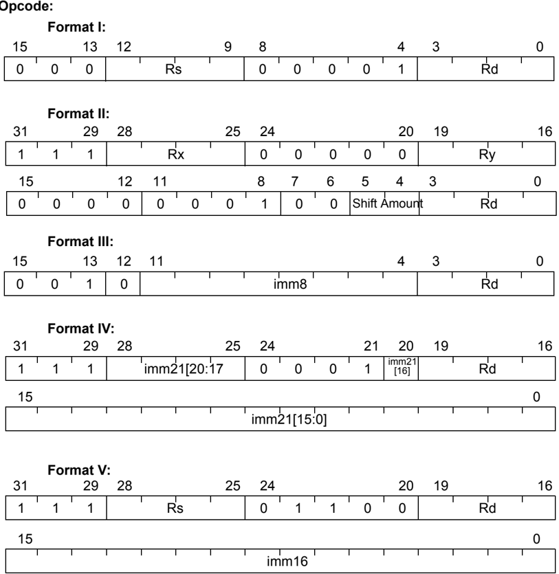
Opcode:
Format I: 15 13 12 9 8 4 3 0 | 0 | 0 | 0 | Rs | 0 | 0 | 0 | 0 | 1 | Rd |
Format II: 31 29 28 25 24 20 19 16 | 1 | 1 | 1 | Rx | 0 | 0 | 0 | 0 | 0 | Ry | 15 12 11 8 7 6 5 4 3 0 | 0 | 0 | 0 | 0 | 0 | 0 | 0 | 1 | 0 | 0 | Shift Amount | Rd |
Format III: 15 13 12 11 4 3 0 | 0 | 0 | 1 | 0 | imm8 | Rd |
Format IV: 31 29 28 25 24 21 20 19 16 | 1 | 1 | 1 | imm21[20:17] | 0 | 0 | 0 | 1 | imm21[16] | Rd | 15 0 | imm21[15:0] |
Format V: 31 29 28 25 24 20 19 16 | 1 | 1 | 1 | Rs | 0 | 1 | 1 | 0 | 0 | Rd | 15 0 | imm16 |
32000D–04/2011 ATMEL® 357
SUB{cond4} – Conditional Subtract
Format I in Architecture revision1 and higher. Format II in Architecture revision 2 and higher.
Description Subtracts a value from a given register and stores the result in destination register if cond4 is true.
Operation: I. If (cond4) then Rd \leftarrow Rd - imm8; Update flags if opcode[f] field is cleared II. If (cond4) then Rd \leftarrow Rx - Ry;
Syntax: I. sub{f}{cond4} Rd, imm II. sub{cond4} Rd, Rx, Ry
Operands: I. cond4 \in {eq, ne, cc/hs, cs/lo, ge, lt, mi, pl, ls, gt, le, hi, vs, vc, qs, al} d \in {0, 1, ..., 15} imm \in {-128, -127, ..., 127} II. cond4 \in {eq, ne, cc/hs, cs/lo, ge, lt, mi, pl, ls, gt, le, hi, vs, vc, qs, al} {d, x, y} \in {0, 1, ..., 15}
Status Flag: K = SE(imm8) Flags only affected if format I and (cond4) is true and F parameter is given Q: Not affected V: V \leftarrow (Rd[31] \wedge \negK[31] \wedge \negRES[31]) \vee (\negRd[31] \wedge K[31] \wedge RES[31]) N: N \leftarrow RES[31] Z: Z \leftarrow (RES[31:0] == 0) C: C \leftarrow \negRd[31] \wedge K[31] \vee K[31] \wedge RES[31] \vee RES[31] \wedge \negRd[31]
Opcode:
Format I:I
 31 29 28 26 25 24 20 19 16
| 1 | 1 | 1 | 1 | 0 | 1 | F | 1 | 1 | 0 | 1 | 1 | Rd |
15 12 11 8 7 0
| 0 | 0 | 0 | 0 | cond4 | imm8 |
358 AVR32 32000D–04/2011
Format II:
 Example:
subfeq R3, 5 performs R3 \leftarrow R3 - 5 and sets flags accordingly if Z flag set.
subeq R5, 7 performs R5 \leftarrow R5 - 5 if Z flag set. Flags are not affected.
32000D-04/2011 ATMEL® 359
AMEL
SUBHH.W– Subtract Halfwords into Word
Description Subtracts the two halfword registers specified and stores the result in the destination word-register. The halfword registers are selected as either the high or low part of the operand registers.
Operation: I. If (Rx-part == t) then operand1 = SE(Rx[31:16]) else operand1 = SE(Rx[15:0]); If (Ry-part == t) then operand2 = SE(Ry[31:16]) else operand2 = SE(Ry[15:0]); Rd \leftarrow operand1 - operand2;
Syntax: I. subhh.wRd, Rx:, Ry:
Operands: I. {d, x, y} \in {0, 1, ..., 15} part \in {t,b}
Status Flags: OP1 = operand1, OP2 = operand2 Q: Not affected V: V \leftarrow (OP1[31] \land \negOP2[31] \land \negRES[31]) \lor (\negOP1[31] \land OP2[31] \land RES[31]) N: N \leftarrow RES[31] Z: Z \leftarrow (RES[31:0] == 0) C: C \leftarrow \negOP1[31] \land OP2[31] \lor OP2[31] \land RES[31] \lor \negOP1[31] \land RES[31]
Opcode:
 \begin{tabular}{|c|c|c|c|c|c|c|c|c|c|c|c|c|c|c|c|c|c|c|c|c|c|c|c|c|c|c|c|c|c|c|c|}
\hline
31 & & 29 & 28 & & & & & 25 & 24 & & & & & & & 20 & 19 & & & & & & & & & & & 16 \
\hline
1 & 1 & 1 & \multicolumn{5}{|c|}{Rx} & \multicolumn{6}{|c|}{0 0 0 0 0 0} & \multicolumn{7}{|c|}{Ry} \
\hline
15 & & & & & & 12 & 11 & & & & & & & & & 6 & 5 & 4 & 3 & & & & & & & & 0 \
\hline
0 & 0 & 0 & 0 & 1 & 1 & 1 & 1 & 0 & 0 & X & Y & \multicolumn{7}{|c|}{Rd} \
\hline
\end{tabular}
Example: subhh.wR10, R2:t, R3:b will perform R10 \leftarrow SE(R2[31:16]) - SE(R3[15:0])
360 AVR32 32000D-04/2011
SWAP.B – Swap Bytes
Description Swaps different parts of a register.
Operation: I. Temp \leftarrow Rd; Rd[31:24] \leftarrow Temp[7:0]; Rd[23:16] \leftarrow Temp[15:8]; Rd[15:8] \leftarrow Temp[23:16]; Rd[7:0] \leftarrow Temp[31:24];
Syntax: I. swap.b Rd
Operands: I. d \in {0, 1, ..., 15}
Status Flags: Q: Not affected. V: Not affected. N: Not affected. Z: Not affected. C: Not affected.
Opcode:
 32000D–04/2011
ATMEL®
361
SWAP.BH – Swap Bytes in Halfword
Description
Swaps different parts of a register.
Operation:
I.
Temp ← Rd;
Rd[31:24] ← Temp[23:16];
Rd[23:16] ← Temp[31:24];
Rd[15:8] ← Temp[7:0];
Rd[7:0] ← Temp[15:8];
Syntax:
I.
swap.bhRd
Operands:
I.
d ∈ {0, 1, ..., 15}
Status Flags:
Q: Not affected.
V: Not affected.
N: Not affected.
Z: Not affected.
C: Not affected.
Opcode:

SWAP.H – Swap Halfwords
Description Swaps different parts of a register.
Operation: I. Temp \leftarrow Rd; Rd[31:16] \leftarrow Temp[15:0]; Rd[15:0] \leftarrow Temp[31:16];
Syntax: I. swap.h Rd
Operands: I. d \in {0, 1, ..., 15}
Status Flags: Q: Not affected. V: Not affected. N: Not affected. Z: Not affected. C: Not affected.
Opcode:
\begin{tabular}{|c|c|c|c|c|c|c|c|c|c|c|c|c|c|c|c|} \hline 15 & & 13 & 12 & & & & 9 & 8 & & & & 4 & 3 & & 0 \ \hline 0 & 1 & 0 & 1 & 1 & 1 & 0 & 0 & 1 & 0 & 1 & 0 & \multicolumn{4}{c|}{Rd} \ \hline \end{tabular}
32000D–04/2011 363
ATML
SYNC – Synchronize memory
Description Finish all pending memory accesses and empties write buffers. The semantic of Op8 is IMPLEMENTATION DEFINED.
Operation: I. Finishes all pending memory operations.
Syntax: I. sync Op8
Operands: I. 0 ≤ Op8 ≤ 255
Status Flags: Q: Not affected. V: Not affected. N: Not affected. Z: Not affected. C: Not affected.
Opcode:
 364 AVR32 32000D-04/2011
TLBR – Read TLB Entry
Description Read the contents of the addressed ITLB or DTLB Entry into TLBEHI and TLBELO.
Operation: I. if (TLBEHI[I] == 1) {TLBEHI, TLBELO} \leftarrowITLB[MMUCR[IRP]]; else {TLBEHI, TLBELO} \leftarrowDTLB[MMUCR[DRP]];
Syntax: I. tlbr
Operands: None
Status Flags: Q: Not affected. V: Not affected. N: Not affected. Z: Not affected. C: Not affected.
Opcode: 15 9 8 4 3 0 | 1 | 1 | 0 | 1 | 0 | 1 | 1 | 0 | 0 | 1 | 0 | 0 | 0 | 0 | 1 | 1 |
Note: This instruction can only be executed in a privileged mode.
32000D-04/2011 ATMEL 365

TLBS – Search TLB For Entry
Description
Search the addressed TLB for an entry matching TLB Entry High and Low (TLBEHI/TLBELO) registers. Return a pointer to the entry in MMUCR[IRP] or MMUCR[DRP] if a match found, otherwise set the Not Found bit in the MMU control register, MMUCR[N].
Operation:
I. MMUCR[N] \leftarrow1; if (TLBEHI[I] == 1) TlbToSearch \leftarrowITLB; else TlbToSearch \leftarrowDTLB; endif;
for (i = 0 to TLBToSearchEntries-1) if ( Compare(TlbToSearch[i]${VPN}$, VA, TlbToSearch[i]${SZ}$, TlbToSearch[i]${V}$) ) // VPN and VA matches for the given page size and entry valid if ( SharedVMM or (PrivateVMM and ( TlbToSearch[i]${G}$ or (TlbToSearch[i]$_{ASID}$==TLBEHI[ASID]) ) ) ) ptr \leftarrow i; MMUCR[N] \leftarrow0; endif; endif; endfor; if (TLBEHI[I] == 1) MMUCR[IRP] \leftarrowptr; else MMUCR[DRP] \leftarrowptr; endif;
Syntax:
I. tlbs
Operands:
None
Status Flags:
Q: Not affected. V: Not affected. N: Not affected. Z: Not affected. C: Not affected.
Opcode: 15 9 8 4 3 0 ┌───┼───┼───┼───┼───┐ │ 1 │ 1 │ 0 │ 1 │ 0 │ 1 │ 1 │ 0 │ 0 │ 1 │ 0 │ 1 │ 0 │ 0 │ 1 │ 1 │ └───┴───┴───┴───┴───┴───┴───┴───┴───┴───┴───┴───┴───┴───┴───┘
Note: This instruction can only be executed in a privileged mode.
32000D-04/2011 367
TLBW – Write TLB Entry
Description Write the contents of the TLB Entry High and Low (TLBEHI/TLBELO) registers into the addressed TLB entry.
Operation: I. if (TLBEHI[I] == 1) ITLB[MMUCR[IRP]] ← {TLBEHI, TLBELO}; else ITLB[MMUCR[DRP]] ← {TLBEHI, TLBELO};
Syntax: I. tlbw
Operands: None
Status Flags: Q: Not affected. V: Not affected. N: Not affected. Z: Not affected. C: Not affected.
Opcode:
 Note:
This instruction can only be executed in a privileged mode.
368 AVR32 32000D–04/2011
TNBZ – Test if No Byte is Equal to Zero
Description If any of the bytes 0,1,2,3 in the word is zero, the SR[Z] flag is set.
Operation: I. if (Rd[31:24] == 0 \lor Rd[23:16] == 0 \lor Rd[15:8] == 0 \lor Rd[7:0] == 0 ) SR[Z] \leftarrow 1; else SR[Z] \leftarrow 0;
Syntax: I. tnbz Rd
Operands: I. d \in {0, 1, ..., 15}
Status Flags: Q: Not affected. V: Not affected. N: Not affected. Z: Z \leftarrow (Rd[31:24] == 0 \lor Rd[23:16] == 0 \lor Rd[15:8] == 0 \lor Rd[7:0] == 0 ) C: Not affected.
Opcode:
\begin{tabular}{|c|c|c|c|c|c|c|c|c|c|c|c|c|c|c|c|} \hline 15 & & 13 & 12 & & & & 9 & 8 & & & & 4 & 3 & & 0 \ \hline 0 & 1 & 0 & 1 & 1 & 1 & 0 & 0 & 1 & 1 & 1 & 0 & & & Rd & \ \hline \end{tabular}
32000D–04/2011 ATMEL 369
TST – Test Register
Description
Test register. Used to check if a subset of a register includes one or more set bits. No writeback of the result is performed, but the flags are set.
Operation:
I. Rd \wedge Rs;
Syntax:
I. tst Rd, Rs
Operands:
I. {d,s} \in {0, 1, ..., 15}
Status Flags
Q: Not affected V: Not affected N: N \leftarrow RES[31] Z: Z \leftarrow (RES[31:0] == 0) C: Not affected
Opcode(s)
\begin{tabular}{|c|c|c|c|c|c|c|c|c|c|c|c|c|c|c|c|} \hline 15 & & 13 & 12 & & & & 9 & 8 & & & & 4 & 3 & & 0 \ \hline 0 & 0 & 0 & \multicolumn{4}{c|}{Rs} & 0 & 0 & 1 & 1 & 1 & \multicolumn{2}{c|}{Rd} & \ \hline \end{tabular}
370 AVR32 32000D–04/2011

XCHG – Exchange Register and Memory
Description
Reads a word from memory pointed to by Rx into register Rd, and writes the value of register Ry to memory. This instruction can be used to implement binary semaphores (mutexes). The stcond instruction should be used to implement counting semaphores.
Operation:
I. Temp \leftarrow *(Rx); *(Rx) \leftarrow Ry; Rd \leftarrow Temp;
Syntax:
I. xchg Rd, Rx, Ry
Operands:
I. {d,x,y} \in {0, 1, ..., 14}
Status Flags:
Q: Not affected V: Not affected N: Not affected Z: Not affected C: Not affected
Opcode:
 Note:
If R15 is used as Rd, Rx or Ry, the result is UNDEFINED.
If Rd = Ry, the result is UNDEFINED.
If Rd = Rx, the result is UNDEFINED.
32000D–04/2011 ATMEL® 371
372 AVR32 32000D–04/2011
AVR32
10. Revision History
10.1 Rev. 32000A-02/2006
- Initial version.
10.2 Rev. 32000B-11/2007
- Improved description of RETE in Instruction Set Chapter.
- Corrected description of STC.D in Instruction Set Chapter.
- Added micro-TLB miss performance counting.
- Added clear-on-compare functionality to COUNT system register
- Updated MPU description to match implementation
- Added new architecture revision 2 instructions
10.3 Rev. 32000C-08/2009
- Corrected typos in the MOVH instruction description.
- Corrected Reset address typo in chapter 7.3.1.1
- Corrected typos in RETE, DIVS and DIVU detailed instruction set descriptions.
- Described new architecture revision 3 secure execution state.
- Automatic clear of COUNT on COMPARE match can now be overridden, usually by writing a bit in the implementation's CPUCR register.
10.4 Rev. 32000D-04/2011
- FlashVault™ description added
- Instruction syntax: Each Ri has been replaced by Ri: in the instruction set summary and descriptions
- Added description of bit 7 in Op8 in sleep instruction
- Parantheses added to shift instruction descriptions to clarify the order of the operations
- Added cond4 to ld.sb, ld.ub, ld.sh, ld.uh, ld.w, st.b, st.h, st.w instruction description syntax
- SE replaced by ZE in st.w{cond4} in the Instruction Set Summary table
32000D–04/2011 373
374 AVR32 32000D–04/2011
AVR32
Table of contents
- Feature Summary ........ 1
- 1 Introduction ........ 2
- 1.1 The AVR family ........ 2
- 1.2 The AVR32 Microprocessor Architecture ........ 2
- 1.3 Microarchitectures ........ 4
- 2 Programming Model ........ 5
- 2.1 Data Formats ........ 5
- 2.2 Data Organization ........ 5
- 2.3 Instruction Organization ........ 6
- 2.4 Processor States ........ 7
- 2.5 Entry and Exit Mechanism ........ 8
- 2.6 Register File ........ 8
- 2.7 The Stack Pointer ........ 10
- 2.8 The Program Counter ........ 11
- 2.9 The Link Register ........ 11
- 2.10 The Status Register ........ 11
- 2.11 System registers ........ 14
- 2.12 Recommended Call Convention ........ 26
- 3 Java Extension Module ........ 27
- 3.1 The AVR32 Java Virtual Machine ........ 27
- 4 Secure state ........ 31
- 4.1 Mechanisms implementing the Secure State ........ 31
- 4.2 Secure state programming model ........ 32
- 4.3 Details on Secure State implementation ........ 33
- 5 Memory Management Unit ........ 35
- 5.1 Memory map in systems with MMU ........ 35
- 5.2 Understanding the MMU ........ 37
- 5.3 Operation of the MMU and MMU exceptions ........ 47
- 6 Memory Protection Unit ........ 51
- 6.1 Memory map in systems with MPU ........ 51
- 6.2 Understanding the MPU ........ 51
- 6.3 Example of MPU functionality ........ 55
32000D–04/2011 i
-
7 Performance counters ........ 57
-
7.1 Overview ........ 57
-
7.2 Registers ........ 57
-
7.3 Monitorable events ........ 59
-
7.4 Usage ........ 60
-
8 Event Processing ........ 63
-
8.1 Event handling in AVR32A ........ 63
-
8.2 Event handling in AVR32B ........ 64
-
8.3 Entry points for events ........ 66
-
8.4 Event priority ........ 92
-
8.5 Event handling in secure state ........ 92
-
9 AVR32 RISC Instruction Set ........ 93
-
9.1 Instruction Set Nomenclature ........ 93
-
9.2 Instruction Formats ........ 97
-
9.3 Instruction Set Summary ........ 106
-
9.4 Base Instruction Set Description ........ 122
-
10 Revision History ........ 373
-
10.1 Rev. 32000A-02/2006 ........ 373
-
10.2 Rev. 32000B-11/2007 ........ 373
-
10.3 Rev. 32000C-08/2009 ........ 373
-
10.4 Rev. 32000D-04/2011 ........ 373
-
Table of contents ........ i
ii AVR32 32000D–04/2011
ATMEL
Atmel Corporation 2325 Orchard Parkway San Jose, CA 95131 USA Tel: (+1)(408) 441-0311 Fax: (+1)(408) 487-2600 www.atmel.com
Atmel Asia Limited Unit 1-5 & 16, 19/F BEA Tower, Millennium City 5 418 Kwun Tong Road Kwun Tong, Kowloon HONG KONG Tel: (+852) 2245-6100 Fax: (+852) 2722-1369
Atmel Munich GmbH Business Campus Parkring 4 D-85748 Garching b. Munich GERMANY Tel: (+49) 89-31970-0 Fax: (+49) 89-3194621
Atmel Japan 9F, Tonetsu Shinkawa Bldg. 1-24-8 Shinkawa Chuo-ku, Tokyo 104-0033 JAPAN Tel: (+81)(3) 3523-3551 Fax: (+81)(3) 3523-7581
© 2011 Atmel Corporation. All rights reserved. / Rev. CORP072610
Atmel®, logo and combinations thereof, and others are registered trademarks or trademarks of Atmel Corporation or its subsidiaries. Other terms and product names may be trademarks of others.
Disclaimer: The information in this document is provided in connection with Atmel products. No license, express or implied, by estoppel or otherwise, to any intellectual property right is granted by this document or in connection with the sale of Atmel products. EXCEPT AS SET FORTH IN THE ATMEL TERMS AND CONDITIONS OF SALES LOCATED ON THE ATMEL WEBSITE, ATMEL ASSUMES NO LIABILITY WHATSOEVER AND DISCLAIMS ANY EXPRESS, IMPLIED OR STATUTORY WARRANTY RELATING TO ITS PRODUCTS INCLUDING, BUT NOT LIMITED TO, THE IMPLIED WARRANTY OF MERCHANTABILITY, FITNESS FOR A PARTICULAR PURPOSE, OR NON-INFRINGEMENT. IN NO EVENT SHALL ATMEL BE LIABLE FOR ANY DIRECT, INDIRECT, CONSEQUENTIAL, PUNITIVE, SPECIAL OR INCIDENTAL DAMAGES (INCLUDING, WITHOUT LIMITATION, DAMAGES FOR LOSS AND PROFITS, BUSINESS INTERRUPTION, OR LOSS OF INFORMATION) ARISING OUT OF THE USE OR INABILITY TO USE THIS DOCUMENT, EVEN IF ATMEL HAS BEEN ADVISED OF THE POSSIBILITY OF SUCH DAMAGES. Atmel makes no representations or warranties with respect to the accuracy or completeness of the contents of this document and reserves the right to make changes to specifications and product descriptions at any time without notice. Atmel does not make any commitment to update the information contained herein. Unless specifically provided otherwise, Atmel products are not suitable for, and shall not be used in, automotive applications. Atmel products are not intended, authorized, or warranted for use as components in applications intended to support or sustain life.
32000D-04/2011