10 Applications, Implementation, and Layout
Note
Information in the following applications sections is not part of the TI component specification, and TI does not warrant its accuracy or completeness. TI’s customers are responsible for determining suitability of components for their purposes. Customers should validate and test their design implementation to confirm system functionality.
10.1 TI Reference Design
The TI Reference Design Library is a robust reference design library spanning analog, embedded processor, and connectivity. Created by TI experts to help you jump start your system design, all reference designs include schematic or block diagrams, BOMs, and design files to speed your time to market. Search and download designs at Select TI reference designs.
11 Device and Documentation Support
11.1 Getting Started
This section gives a brief overview of the steps to take when first developing for a C28x device. For more detail on each of these steps, see the following:
11.2 Device and Development Support Tool Nomenclature
To designate the stages in the product development cycle, TI assigns prefixes to the part numbers of all TMS320™ DSP devices and support tools. Each TMS320 DSP commercial family member has one of three prefixes: TMX, TMP, or TMS (for example, TMS320F2810). Texas Instruments recommends two of three possible prefix designators for its support tools: TMDX and TMDS. These prefixes represent evolutionary stages of product development from engineering prototypes (TMX/TMDX) through fully qualified production devices/tools (TMS/TMDS).
TMX Experimental device that is not necessarily representative of the final device’s electrical specifications
TMP Final silicon die that conforms to the device’s electrical specifications but has not completed quality and reliability verification
TMS Fully qualified production device
Support tool development evolutionary flow:
TMDX Development-support product that has not yet completed Texas Instruments internal qualification testing
TMDS Fully qualified development-support product
TMX and TMP devices and TMDX development-support tools are shipped against the following disclaimer:
"Developmental product is intended for internal evaluation purposes."
TMS devices and TMDS development-support tools have been characterized fully, and the quality and reliability of the device have been demonstrated fully. TI’s standard warranty applies.
Predictions show that prototype devices (TMX or TMP) have a greater failure rate than the standard production devices. Texas Instruments recommends that these devices not be used in any production system because their expected end-use failure rate still is undefined. Only qualified production devices are to be used.
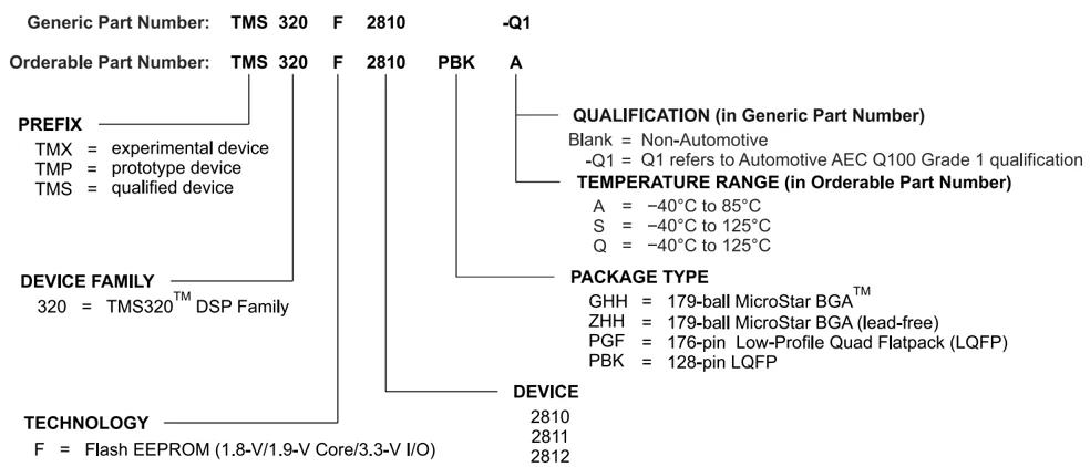
TI device nomenclature also includes a suffix with the device family name. This suffix indicates the package type (for example, PBK) and temperature range (for example, A). Figure 11-1 provides a legend for reading the complete device name for any TMS320F281x family member.
For device part numbers and further ordering information, see the Package Option Addendum of this document, the TI website (www.ti.com), or contact your TI sales representative.
For additional description of the device nomenclature markings on the die, see the TMS320F281x DSPs Silicon Errata.
148 Submit Document Feedback
Product Folder Links: TMS320F2810 TMS320F2810-Q1 TMS320F2811 TMS320F2811-Q1 TMS320F2812 TMS320F2812-Q1

TMS320F2810, TMS320F2810-Q1, TMS320F2811, TMS320F2811-Q1
TMS320F2812, TMS320F2812-Q1
Generic Part Number: TMS 320 F 2810 -Q1
Orderable Part Number: TMS 320 F 2810 PBK A
PREFIX
- TMX = experimental device
- TMP = prototype device
- TMS = qualified device
DEVICE FAMILY
320 = TMS320™ DSP Family
TECHNOLOGY
F = Flash EEPROM (1.8-V/1.9-V Core/3.3-V I/O)
QUALIFICATION (in Generic Part Number)
- Blank = Non-Automotive
- -Q1 = Q1 refers to Automotive AEC Q100 Grade 1 qualification
TEMPERATURE RANGE (in Orderable Part Number)
- A = -40°C to □□°C
- S = -40°C to □□□°C
- Q = -40°C to □□□°C
PACKAGE TYPE
- GHH = 179-ball MicroStar BGA™
- ZHH = 179-ball MicroStar BGA (lead-free)
- PGF = 176-pin Low-Profile Quad Flatpack (LQFP)
- PBK = 128-pin LQFP
DEVICE
- 2810
- 2811
- 2812
Figure 11-1. TMS320F281x Device Nomenclature
11.3 Tools and Software
TI offers an extensive line of development tools. Some of the tools and software to evaluate the performance of the device, generate code, and develop solutions are listed below. To view all available tools and software, visit the Tools & software page for each device.
Development Tools
TMS320F2812 eZdsp Start Kit (DSK)
The F2812 eZdsp™ is a standalone module that lets evaluators examine certain characteristics of the F2812 digital signal processor (DSP) to determine if this DSP meets their application requirements. This module has a single chip parallel port to JTAG scan controller. Therefore the module can be operated without additional development tools such as an emulator. Furthermore, the module is an excellent platform to develop, demonstrate, and run software for the F2812 processor.
Uniflash Standalone Flash Tool
CCS Uniflash is a standalone tool used to program on-chip flash memory on TI MCUs.
Software Tools
controlSUITE™ Software Suite: Software and Development Tools for C2000™ Microcontrollers
controlSUITE™ for C2000™ microcontrollers is a cohesive set of software infrastructure, tools, and documentation designed to minimize system development time. From device-specific drivers and support software to complete examples in sophisticated system applications, controlSUITE provides the needed resources at every stage of development and evaluation.
Code Composer Studio™ (CCS) Integrated Development Environment (IDE) for C2000 Microcontrollers
Code Composer Studio is an integrated development environment (IDE) that supports TI's Microcontroller and Embedded Processors portfolio. Code Composer Studio comprises a suite of tools used to develop and debug embedded applications. It includes an optimizing C/C++ compiler, source code editor, project build environment, debugger, profiler, and many other features. The intuitive IDE provides a single user interface taking the user through each step of the application development flow. Familiar tools and interfaces allow users to get started faster than ever before. Code Composer Studio combines the advantages of the Eclipse software framework with advanced embedded debug capabilities from TI resulting in a compelling feature-rich development environment for embedded developers.
Submit Document Feedback 149
Models
Various models are available for download from the product Tools & Software pages. These include I/O Buffer Information Specification (IBIS) Models and Boundary-Scan Description Language (BSDL) Models. To view all available models, visit the Models section of the Tools & Software page for each device.
11.4 Documentation Support
To receive notification of documentation updates, navigate to the device product folder on ti.com. In the upper right corner, click on Alert me to register and receive a weekly digest of any product information that has changed. For change details, review the revision history included in any revised document.
The current documentation that describes the processor, related peripherals, and other technical collateral is listed below.
Errata
TMS320F281x DSPs Silicon Errata describes the advisories and usage notes for different versions of silicon.
CPU User's Guides
TMS320C28x CPU and Instruction Set Reference Guide describes the central processing unit (CPU) and the assembly language instructions of the TMS320C28x fixed-point digital signal processors (DSPs). It also describes emulation features available on these DSPs.
Peripheral Guides
C2000 Real-Time Control Peripherals Reference Guide describes the peripheral reference guides of the 28x digital signal processors (DSPs).
TMS320x281x DSP Analog-to-Digital Converter (ADC) Reference Guide describes the ADC module. The module is a 12-bit pipelined ADC. The analog circuits of this converter, referred to as the core in this document, include the front-end analog multiplexers (MUXs), sample-and-hold (S/H) circuits, the conversion core, voltage regulators, and other analog supporting circuits. Digital circuits, referred to as the wrapper in this document, include programmable conversion sequencer, result registers, interface to analog circuits, interface to device peripheral bus, and interface to other on-chip modules.
TMS320x281x DSP Boot ROM Reference Guide describes the purpose and features of the bootloader (factory-programmed boot-loading software). It also describes other contents of the device on-chip boot ROM and identifies where all of the information is located within that memory.
TMS320x281x DSP Event Manager (EV) Reference Guide describes the EV modules that provide a broad range of functions and features that are particularly useful in motion control and motor control applications. The EV modules include general-purpose (GP) timers, full-compare/PWM units, capture units, and quadrature-encoder pulse (QEP) circuits.
TMS320x281x DSP External Interface (XINTF) Reference Guide describes the external interface (XINTF) of the 281x digital signal processors (DSPs).
TMS320x281x DSP Multichannel Buffered Serial Port (McBSP) Reference Guide describes the McBSP available on the 281x devices. The McBSPs allow direct interface between a DSP and other devices in a system.
TMS320x281x DSP System Control and Interrupts Reference Guide describes the various interrupts and system control features of the 281x digital signal processors (DSPs).
TMS320x281x Enhanced Controller Area Network (eCAN) Reference Guide describes the eCAN that uses established protocol to communicate serially with other controllers in electrically noisy environments. With 32 fully configurable mailboxes and time-stamping feature, the eCAN module provides a versatile and robust serial communication interface. The eCAN module implemented in the C28x DSP is compatible with the ISO11898-1 (CAN 2.0B) standard (active).
TMS320x281x Serial Communications Interface (SCI) Reference Guide describes the SCI that is a two-wire asynchronous serial port, commonly known as a UART. The SCI modules support digital communications between the CPU and other asynchronous peripherals that use the standard non-return-to-zero (NRZ) format.
150 Submit Document Feedback
Product Folder Links: TMS320F2810 TMS320F2810-Q1 TMS320F2811 TMS320F2811-Q1 TMS320F2812 TMS320F2812-Q1

TMS320F2810, TMS320F2810-Q1, TMS320F2811, TMS320F2811-Q1
TMS320F2812, TMS320F2812-Q1
TMS320x281x Serial Peripheral Interface Reference Guide describes the SPI—a high-speed synchronous serial input/output (I/O) port that allows a serial bit stream of programmed length (one to sixteen bits) to be shifted into and out of the device at a programmed bit-transfer rate. The SPI is used for communications between the DSP controller and external peripherals or another controller.
Tools Guides
TMS320C28x Assembly Language Tools v18.12.0.LTS User's Guide describes the assembly language tools (assembler and other tools used to develop assembly language code), assembler directives, macros, common object file format, and symbolic debugging directives for the TMS320C28x device.
TMS320C28x Optimizing C/C++ Compiler v18.12.0.LTS User's Guide describes the TMS320C28x C/C++ compiler. This compiler accepts ANSI standard C/C++ source code and produces TMS320 DSP assembly language source code for the TMS320C28x device.
TMS320C28x DSP/BIOS 5.x Application Programming Interface (API) Reference Guide describes development using DSP/BIOS.
Application Reports
The SMT & packaging application notes website lists documentation on TI’s surface mount technology (SMT) and application notes on a variety of packaging-related topics.
Programming Examples for the TMS320x28xx eCAN Application Report contains several programming examples to illustrate how the eCAN module is set up for different modes of operation. The objective is to help you come up to speed quickly in programming the eCAN. All programs have been extensively commented to aid easy understanding.
F2810, F2811, and F2812 ADC Calibration Application Report describes a method for improving the absolute accuracy of the 12-bit analog-to-digital converter (ADC) found on the F2810/F2811/F2812 devices. Due to inherent gain and offset errors, the absolute accuracy of the ADC is impacted. The methods described in this application note can improve the absolute accuracy of the ADC to achieve levels better than 0.5%. This application note is accompanied by an example program (ADCcalibration, spra989.zip) that executes from RAM on the F2812 eZdsp.
An Introduction to IBIS (I/O Buffer Information Specification) Modeling discusses various aspects of IBIS including its history, advantages, compatibility, model generation flow, data requirements in modeling the input/output structures and future trends.
Semiconductor Packing Methodology describes the packing methodologies employed to prepare semiconductor devices for shipment to end users.
Calculating Useful Lifetimes of Embedded Processors provides a methodology for calculating the useful lifetime of TI embedded processors (EPs) under power when used in electronic systems. It is aimed at general engineers who wish to determine if the reliability of the TI EP meets the end system reliability requirement.
Calculating FIT for a Mission Profile explains how to use TI's reliability de-rating tools to calculate a component-level FIT under power-on conditions for a system mission profile.
Semiconductor and IC Package Thermal Metrics describes traditional and new thermal metrics and puts their application in perspective with respect to system-level junction temperature estimation.
Serial Flash Programming of C2000™ Microcontrollers discusses using a flash kernel and ROM loaders for serial programming a device.
11.5 Support Resources
TI E2E™ support forums are an engineer's go-to source for fast, verified answers and design help — straight from the experts. Search existing answers or ask your own question to get the quick design help you need.
Linked content is provided "AS IS" by the respective contributors. They do not constitute TI specifications and do not necessarily reflect TI's views; see TI's Terms of Use.
Submit Document Feedback 151

11.6 Trademarks
Code Composer Studio™, DSP/BIOS™, MicroStar BGA™, and are trademarks of TI. C2000™, Piccolo™, TMS320C2000™, TMS320™, controlSUITE™, TI E2E™ are trademarks of Texas Instruments. eZdsp™ is a trademark of Spectrum Digital Incorporated. All trademarks are the property of their respective owners.
11.7 Electrostatic Discharge Caution
This integrated circuit can be damaged by ESD. Texas Instruments recommends that all integrated circuits be handled with appropriate precautions. Failure to observe proper handling and installation procedures can cause damage.
ESD damage can range from subtle performance degradation to complete device failure. Precision integrated circuits may be more susceptible to damage because very small parametric changes could cause the device not to meet its published specifications.
11.8 Glossary
TI Glossary This glossary lists and explains terms, acronyms, and definitions.
12 Mechanical, Packaging, and Orderable Information
12.1 Packaging Information
The following pages include mechanical, packaging, and orderable information. This information is the most current data available for the designated devices. This data is subject to change without notice and revision of this document. For browser-based versions of this data sheet, refer to the left-hand navigation.
To learn more about TI packaging, visit the Packaging information website.
TMS320F2810, TMS320F2810-Q1, TMS320F2811, TMS320F2811-Q1 TMS320F2812, TMS320F2812-Q1 SPRS174V – APRIL 2001 – REVISED FEBRUARY 2021
Copyright © 2021 Texas Instruments Incorporated Submit Document Feedback 153 Product Folder Links: TMS320F2810 TMS320F2810-Q1 TMS320F2811 TMS320F2811-Q1 TMS320F2812 TMS320F2812-Q1

PACKAGE OPTION ADDENDUM
18-Sep-2026
PACKAGING INFORMATION
| Orderable part number | Status (1) | Material type (2) | Package | Pins | Package qty | Carrier | RoHS (3) | Lead finish/ Ball material (4) | MSL rating/ Peak reflow (5) | Op temp (°C) | Part marking (6) |
|---|---|---|---|---|---|---|---|---|---|---|---|
| TMS320F2810PBKA | Active | Production | LQFP (PBK) | 128 | 90 | JEDEC TRAY (5+1) | Yes | NIPDAU | Level-2-260C-1 YEAR | -40 to 85 | 320F2810PBKA TMS |
| TMS320F2810PBKA.A | Active | Production | LQFP (PBK) | 128 | 90 | JEDEC TRAY (5+1) | Yes | NIPDAU | Level-2-260C-1 YEAR | -40 to 85 | 320F2810PBKA TMS |
| TMS320F2810PBKAG4 | Active | Production | LQFP (PBK) | 128 | 90 | JEDEC TRAY (5+1) | Yes | NIPDAU | Level-2-260C-1 YEAR | -40 to 125 | 320F2810PBKA TMS |
| TMS320F2810PBKAG4.A | Active | Production | LQFP (PBK) | 128 | 90 | JEDEC TRAY (5+1) | Yes | NIPDAU | Level-2-260C-1 YEAR | -40 to 125 | 320F2810PBKA TMS |
| TMS320F2810PBKQ | Active | Production | LQFP (PBK) | 128 | 90 | JEDEC TRAY (5+1) | Yes | NIPDAU | Level-2-260C-1 YEAR | -40 to 125 | 320F2810PBKQ TMS |
| TMS320F2810PBKQ.A | Active | Production | LQFP (PBK) | 128 | 90 | JEDEC TRAY (5+1) | Yes | NIPDAU | Level-2-260C-1 YEAR | -40 to 125 | 320F2810PBKQ TMS |
| TMS320F2810PBKQR | Active | Production | LQFP (PBK) | 128 | 1000 | LARGE T&R | Yes | NIPDAU | Level-2-260C-1 YEAR | -40 to 125 | 320F2810PBKQ TMS |
| TMS320F2810PBKQR.A | Active | Production | LQFP (PBK) | 128 | 1000 | LARGE T&R | Yes | NIPDAU | Level-2-260C-1 YEAR | -40 to 125 | 320F2810PBKQ TMS |
| TMS320F2810PBKS | Active | Production | LQFP (PBK) | 128 | 90 | JEDEC TRAY (5+1) | Yes | NIPDAU | Level-2-260C-1 YEAR | -40 to 125 | 320F2810PBKS TMS |
| TMS320F2810PBKS.A | Active | Production | LQFP (PBK) | 128 | 90 | JEDEC TRAY (5+1) | Yes | NIPDAU | Level-2-260C-1 YEAR | -40 to 125 | 320F2810PBKS TMS |
| TMS320F2810PBKSG4 | Active | Production | LQFP (PBK) | 128 | 90 | JEDEC TRAY (5+1) | Yes | NIPDAU | Level-2-260C-1 YEAR | -40 to 125 | 320F2810PBKS TMS |
| TMS320F2810PBKSG4.A | Active | Production | LQFP (PBK) | 128 | 90 | JEDEC TRAY (5+1) | Yes | NIPDAU | Level-2-260C-1 YEAR | -40 to 125 | 320F2810PBKS TMS |
| TMS320F2811PBKA | Active | Production | LQFP (PBK) | 128 | 90 | JEDEC TRAY (5+1) | Yes | NIPDAU | Level-2-260C-1 YEAR | -40 to 85 | 320F2811PBKA TMS |
| TMS320F2811PBKA.A | Active | Production | LQFP (PBK) | 128 | 90 | JEDEC TRAY (5+1) | Yes | NIPDAU | Level-2-260C-1 YEAR | -40 to 85 | 320F2811PBKA TMS |
| TMS320F2811PBKAG4 | Active | Production | LQFP (PBK) | 128 | 90 | JEDEC TRAY (5+1) | Yes | NIPDAU | Level-2-260C-1 YEAR | -40 to 125 | 320F2811PBKA TMS |
| TMS320F2811PBKAG4.A | Active | Production | LQFP (PBK) | 128 | 90 | JEDEC TRAY (5+1) | Yes | NIPDAU | Level-2-260C-1 YEAR | -40 to 125 | 320F2811PBKA TMS |
Addendum-Page 1

PACKAGE OPTION ADDENDUM
18-Sep-2026
| Orderable part number | Status (1) | Material type (2) | Package | Pins | Package qty | Carrier | RoHS (3) | Lead finish/ Ball material (4) | MSL rating/ Peak reflow (5) | Op temp (°C) | Part marking (6) |
|---|---|---|---|---|---|---|---|---|---|---|---|
| TMS320F2811PBKQ | Active | Production | LQFP (PBK) | 128 | 90 | JEDEC TRAY (5+1) | Yes | NIPDAU | Level-2-260C-1 YEAR | -40 to 125 | 320F2811PBKQ TMS |
| TMS320F2811PBKQ.A | Active | Production | LQFP (PBK) | 128 | 90 | JEDEC TRAY (5+1) | Yes | NIPDAU | Level-2-260C-1 YEAR | -40 to 125 | 320F2811PBKQ TMS |
| TMS320F2811PBKS | Active | Production | LQFP (PBK) | 128 | 90 | JEDEC TRAY (5+1) | Yes | NIPDAU | Level-2-260C-1 YEAR | -40 to 125 | 320F2811PBKS TMS |
| TMS320F2811PBKS.A | Active | Production | LQFP (PBK) | 128 | 90 | JEDEC TRAY (5+1) | Yes | NIPDAU | Level-2-260C-1 YEAR | -40 to 125 | 320F2811PBKS TMS |
| TMS320F2812GBBA | Active | Production | NFBGA (GBB) | 179 | 160 | JEDEC TRAY (5+1) | No | SNPB | Level-3-220C-168 HR | -40 to 85 | TMS 320F2812GBBA |
| TMS320F2812GBBA.A | Active | Production | NFBGA (GBB) | 179 | 160 | JEDEC TRAY (5+1) | No | SNPB | Level-3-220C-168 HR | -40 to 85 | TMS 320F2812GBBA |
| TMS320F2812GBBAR | Active | Production | NFBGA (GBB) | 179 | 1000 | LARGE T&R | No | SNPB | Level-3-220C-168 HR | -40 to 85 | TMS 320F2812GBBA |
| TMS320F2812GBBAR.A | Active | Production | NFBGA (GBB) | 179 | 1000 | LARGE T&R | No | SNPB | Level-3-220C-168 HR | -40 to 85 | TMS 320F2812GBBA |
| TMS320F2812GBBS | Active | Production | NFBGA (GBB) | 179 | 160 | EIAJ TRAY (5+1) | No | SNPB | Level-3-220C-168 HR | -40 to 125 | TMS 320F2812GBBS |
| TMS320F2812GBBS.A | Active | Production | NFBGA (GBB) | 179 | 160 | EIAJ TRAY (5+1) | No | SNPB | Level-3-220C-168 HR | -40 to 125 | TMS 320F2812GBBS |
| TMS320F2812PGFA | Active | Production | LQFP (PGF) | 176 | 40 | JEDEC TRAY (5+1) | Yes | NIPDAU | Level-3-260C-168 HR | -40 to 85 | 320F2812PGFA TMS |
| TMS320F2812PGFA.A | Active | Production | LQFP (PGF) | 176 | 40 | JEDEC TRAY (5+1) | Yes | NIPDAU | Level-3-260C-168 HR | -40 to 85 | 320F2812PGFA TMS |
| TMS320F2812PGFAG4 | Active | Production | LQFP (PGF) | 176 | 40 | JEDEC TRAY (5+1) | Yes | NIPDAU | Level-3-260C-168 HR | -40 to 85 | 320F2812PGFA TMS |
| TMS320F2812PGFQ | Active | Production | LQFP (PGF) | 176 | 40 | JEDEC TRAY (5+1) | Yes | NIPDAU | Level-3-260C-168 HR | -40 to 125 | 320F2812PGFQ TMS |
| TMS320F2812PGFQ.A | Active | Production | LQFP (PGF) | 176 | 40 | JEDEC TRAY (5+1) | Yes | NIPDAU | Level-3-260C-168 HR | -40 to 125 | 320F2812PGFQ TMS |
| TMS320F2812PGFS | Active | Production | LQFP (PGF) | 176 | 40 | JEDEC TRAY (5+1) | Yes | NIPDAU | Level-3-260C-168 HR | -40 to 125 | 320F2812PGFS TMS |
| TMS320F2812PGFS.A | Active | Production | LQFP (PGF) | 176 | 40 | JEDEC TRAY (5+1) | Yes | NIPDAU | Level-3-260C-168 HR | -40 to 125 | 320F2812PGFS TMS |
Addendum-Page 2

PACKAGE OPTION ADDENDUM
www.ti.com 18-Sep-2026

| Orderable part number | Status (1) | Material type (2) | Package | Pins | Package qty | Carrier | RoHS (3) | Lead finish/ Ball material (4) | MSL rating/ Peak reflow (5) | Op temp (°C) | Part marking (6) |
|---|---|---|---|---|---|---|---|---|---|---|---|
| TMS320F2812PGFSG4 | Active | Production | LQFP (PGF) | 176 | 40 | JEDEC TRAY (5+1) | Yes | NIPDAU | Level-3-260C-168 HR | -40 to 125 | 320F2812PGFS TMS |
| TMS320F2812PGFSG4.A | Active | Production | LQFP (PGF) | 176 | 40 | JEDEC TRAY (5+1) | Yes | NIPDAU | Level-3-260C-168 HR | -40 to 125 | 320F2812PGFS TMS |
| TMS320F2812ZAYA | Active | Production | NFBGA (ZAY) | 179 | 160 | EIAJ TRAY (5+1) | Yes | SNAGCU | Level-3-260C-168 HR | -40 to 85 | TMS 320F2812ZAYA |
| TMS320F2812ZAYA.A | Active | Production | NFBGA (ZAY) | 179 | 160 | EIAJ TRAY (5+1) | Yes | SNAGCU | Level-3-260C-168 HR | -40 to 85 | TMS 320F2812ZAYA |
| TMS320F2812ZAYAR | Active | Production | NFBGA (ZAY) | 179 | 1000 | LARGE T&R | Yes | SNAGCU | Level-3-260C-168 HR | -40 to 85 | TMS 320F2812ZAYA |
| TMS320F2812ZAYAR.A | Active | Production | NFBGA (ZAY) | 179 | 1000 | LARGE T&R | Yes | SNAGCU | Level-3-260C-168 HR | -40 to 85 | TMS 320F2812ZAYA |
| TMS320F2812ZAYS | Active | Production | NFBGA (ZAY) | 179 | 160 | EIAJ TRAY (5+1) | Yes | SNAGCU | Level-3-260C-168 HR | -40 to 125 | TMS 320F2812ZAYS |
| TMS320F2812ZAYS.A | Active | Production | NFBGA (ZAY) | 179 | 160 | EIAJ TRAY (5+1) | Yes | SNAGCU | Level-3-260C-168 HR | -40 to 125 | TMS 320F2812ZAYS |
(1) Status: For more details on status, see our product life cycle.
(2) Material type: When designated, preproduction parts are prototypes/experimental devices, and are not yet approved or released for full production. Testing and final process, including without limitation quality assurance, reliability performance testing, and/or process qualification, may not yet be complete, and this item is subject to further changes or possible discontinuation. If available for ordering, purchases will be subject to an additional waiver at checkout, and are intended for early internal evaluation purposes only. These items are sold without warranties of any kind.
(3) RoHS values: Yes, No, RoHS Exempt. See the TI RoHS Statement for additional information and value definition.
(4) Lead finish/Ball material: Parts may have multiple material finish options. Finish options are separated by a vertical ruled line. Lead finish/Ball material values may wrap to two lines if the finish value exceeds the maximum column width.
(5) MSL rating/Peak reflow: The moisture sensitivity level ratings and peak solder (reflow) temperatures. In the event that a part has multiple moisture sensitivity ratings, only the lowest level per JEDEC standards is shown. Refer to the shipping label for the actual reflow temperature that will be used to mount the part to the printed circuit board.
(6) Part marking: There may be an additional marking, which relates to the logo, the lot trace code information, or the environmental category of the part.
Multiple part markings will be inside parentheses. Only one part marking contained in parentheses and separated by a "~" will appear on a part. If a line is indented then it is a continuation of the previous line and the two combined represent the entire part marking for that device.
Addendum-Page 3
PACKAGE OPTION ADDENDUM
TEXAS INSTRUMENTS www.ti.com 18-Sep-2026
Important Information and Disclaimer: The information provided on this page represents TI's knowledge and belief as of the date that it is provided. TI bases its knowledge and belief on information provided by third parties, and makes no representation or warranty as to the accuracy of such information. Efforts are underway to better integrate information from third parties. TI has taken and continues to take reasonable steps to provide representative and accurate information but may not have conducted destructive testing or chemical analysis on incoming materials and chemicals. TI and TI suppliers consider certain information to be proprietary, and thus CAS numbers and other limited information may not be available for release.
In no event shall TI's liability arising out of such information exceed the total purchase price of the TI part(s) at issue in this document sold by TI to Customer on an annual basis.
OTHER QUALIFIED VERSIONS OF TMS320F2810, TMS320F2810-Q1, TMS320F2811, TMS320F2811-Q1, TMS320F2812, TMS320F2812-Q1 :
• Catalog : TMS320F2810, TMS320F2811, SM320F2812, TMS320F2812
• Automotive : TMS320F2810-Q1, TMS320F2811-Q1, TMS320F2812-Q1
• Enhanced Product : SM320F2812-EP
• Military : SMJ320F2812, SMJ320F2812
NOTE: Qualified Version Definitions:
• Catalog - TI's standard catalog product
• Automotive - Q100 devices qualified for high-reliability automotive applications targeting zero defects
• Enhanced Product - Supports Defense, Aerospace and Medical Applications
• Military - QML certified for Military and Defense Applications
Addendum-Page 4

PACKAGE MATERIALS INFORMATION
4-Sep-2026
TAPE AND REEL INFORMATION
REEL DIMENSIONS
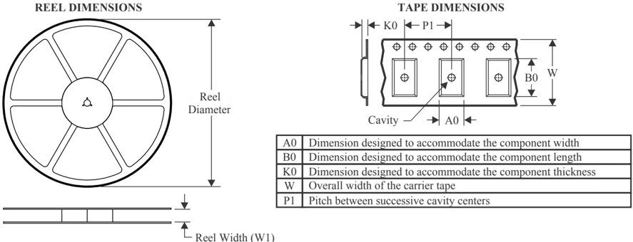
TAPE DIMENSIONS
| A0 | Dimension designed to accommodate the component width |
|---|---|
| B0 | Dimension designed to accommodate the component length |
| K0 | Dimension designed to accommodate the component thickness |
| W | Overall width of the carrier tape |
| P1 | Pitch between successive cavity centers |
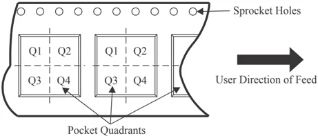
QUADRANT ASSIGNMENTS FOR PIN 1 ORIENTATION IN TAPE
*All dimensions are nominal
| Device | Package Type | Package Drawing | Pins | SPQ | Reel Diameter (mm) | Reel Width W1 (mm) | A0 (mm) | B0 (mm) | K0 (mm) | P1 (mm) | W (mm) | Pin1 Quadrant |
|---|---|---|---|---|---|---|---|---|---|---|---|---|
| TMS320F2812GBBAR | NFBGA | GBB | 179 | 1000 | 330.0 | 24.4 | 12.35 | 12.35 | 2.3 | 16.0 | 24.0 | Q1 |
| TMS320F2812ZAYAR | NFBGA | ZAY | 179 | 1000 | 330.0 | 24.4 | 12.35 | 12.35 | 2.3 | 16.0 | 24.0 | Q1 |
Pack Materials-Page 1
PACKAGE MATERIALS INFORMATION
4-Sep-2026
TAPE AND REEL BOX DIMENSIONS
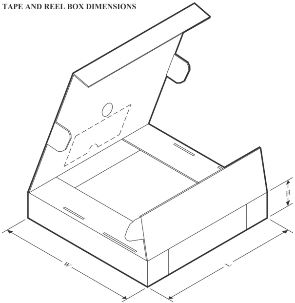
*All dimensions are nominal
| Device | Package Type | Package Drawing | Pins | SPQ | Length (mm) | Width (mm) | Height (mm) |
|---|---|---|---|---|---|---|---|
| TMS320F2812GBBAR | NFBGA | GBB | 179 | 1000 | 336.6 | 336.6 | 41.3 |
| TMS320F2812ZAYAR | NFBGA | ZAY | 179 | 1000 | 336.6 | 336.6 | 41.3 |
Pack Materials-Page 2
PACKAGE MATERIALS INFORMATION
4-Sep-2026
TRAY
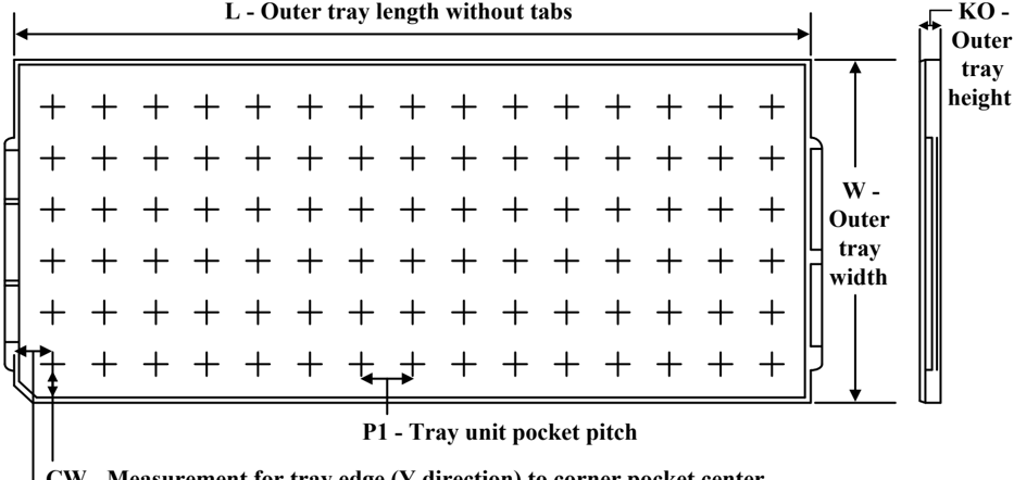
Chamfer on Tray corner indicates Pin 1 orientation of packed units.
*All dimensions are nominal
| Device | Package Name | Package Type | Pins | SPQ | Unit array matrix | Max temperature (°C) | L (mm) | W (mm) | K0 (μm) | P1 (mm) | CL (mm) | CW (mm) |
|---|---|---|---|---|---|---|---|---|---|---|---|---|
| TMS320F2810PBKA | PBK | LQFP | 128 | 90 | 6 x 15 | 150 | 315 | 135.9 | 7620 | 20.3 | 15.4 | 15.4 |
| TMS320F2810PBKA.A | PBK | LQFP | 128 | 90 | 6 x 15 | 150 | 315 | 135.9 | 7620 | 20.3 | 15.4 | 15.4 |
| TMS320F2810PBKAG4 | PBK | LQFP | 128 | 90 | 6 x 15 | 150 | 315 | 135.9 | 7620 | 20.3 | 15.4 | 15.4 |
| TMS320F2810PBKAG4.A | PBK | LQFP | 128 | 90 | 6 x 15 | 150 | 315 | 135.9 | 7620 | 20.3 | 15.4 | 15.4 |
| TMS320F2810PBKQ | PBK | LQFP | 128 | 90 | 6 x 15 | 150 | 315 | 135.9 | 7620 | 20.3 | 15.4 | 15.4 |
| TMS320F2810PBKQ.A | PBK | LQFP | 128 | 90 | 6 x 15 | 150 | 315 | 135.9 | 7620 | 20.3 | 15.4 | 15.4 |
| TMS320F2810PBKS | PBK | LQFP | 128 | 90 | 6 x 15 | 150 | 315 | 135.9 | 7620 | 20.3 | 15.4 | 15.4 |
| TMS320F2810PBKS.A | PBK | LQFP | 128 | 90 | 6 x 15 | 150 | 315 | 135.9 | 7620 | 20.3 | 15.4 | 15.4 |
| TMS320F2810PBKSG4 | PBK | LQFP | 128 | 90 | 6 x 15 | 150 | 315 | 135.9 | 7620 | 20.3 | 15.4 | 15.4 |
| TMS320F2810PBKSG4.A | PBK | LQFP | 128 | 90 | 6 x 15 | 150 | 315 | 135.9 | 7620 | 20.3 | 15.4 | 15.4 |
| TMS320F2811PBKA | PBK | LQFP | 128 | 90 | 6 x 15 | 150 | 315 | 135.9 | 7620 | 20.3 | 15.4 | 15.4 |
| TMS320F2811PBKA.A | PBK | LQFP | 128 | 90 | 6 x 15 | 150 | 315 | 135.9 | 7620 | 20.3 | 15.4 | 15.4 |
| TMS320F2811PBKAG4 | PBK | LQFP | 128 | 90 | 6 x 15 | 150 | 315 | 135.9 | 7620 | 20.3 | 15.4 | 15.4 |
| TMS320F2811PBKAG4.A | PBK | LQFP | 128 | 90 | 6 x 15 | 150 | 315 | 135.9 | 7620 | 20.3 | 15.4 | 15.4 |
| TMS320F2811PBKQ | PBK | LQFP | 128 | 90 | 6 x 15 | 150 | 315 | 135.9 | 7620 | 20.3 | 15.4 | 15.4 |
| TMS320F2811PBKQ.A | PBK | LQFP | 128 | 90 | 6 x 15 | 150 | 315 | 135.9 | 7620 | 20.3 | 15.4 | 15.4 |
| TMS320F2811PBKS | PBK | LQFP | 128 | 90 | 6 x 15 | 150 | 315 | 135.9 | 7620 | 20.3 | 15.4 | 15.4 |
Pack Materials-Page 3
PACKAGE MATERIALS INFORMATION
4-Sep-2026
| Device | Package Name | Package Type | Pins | SPQ | Unit array matrix | Max temperature (°C) | L (mm) | W (mm) | K0 (μm) | P1 (mm) | CL (mm) | CW (mm) |
|---|---|---|---|---|---|---|---|---|---|---|---|---|
| TMS320F2811PBKS.A | PBK | LQFP | 128 | 90 | 6 x 15 | 150 | 315 | 135.9 | 7620 | 20.3 | 15.4 | 15.4 |
| TMS320F2812GBBA | GBB | NFBGA | 179 | 160 | 8 x 20 | 150 | 315 | 135.9 | 7620 | 15.4 | 11.2 | 19.65 |
| TMS320F2812GBBA.A | GBB | NFBGA | 179 | 160 | 8 x 20 | 150 | 315 | 135.9 | 7620 | 15.4 | 11.2 | 19.65 |
| TMS320F2812GBBS | GBB | NFBGA | 179 | 160 | 8 x 20 | 150 | 315 | 135.9 | 7620 | 15.4 | 11.2 | 19.65 |
| TMS320F2812GBBS.A | GBB | NFBGA | 179 | 160 | 8 x 20 | 150 | 315 | 135.9 | 7620 | 15.4 | 11.2 | 19.65 |
| TMS320F2812PGFA | PGF | LQFP | 176 | 40 | 4x10 | 150 | 315 | 135.9 | 7620 | 20.7 | 30.4 | 20.7 |
| TMS320F2812PGFA.A | PGF | LQFP | 176 | 40 | 4x10 | 150 | 315 | 135.9 | 7620 | 20.7 | 30.4 | 20.7 |
| TMS320F2812PGFAG4 | PGF | LQFP | 176 | 40 | 4x10 | 150 | 315 | 135.9 | 7620 | 20.7 | 30.4 | 20.7 |
| TMS320F2812PGFQ | PGF | LQFP | 176 | 40 | 4x10 | 150 | 315 | 135.9 | 7620 | 20.7 | 30.4 | 20.7 |
| TMS320F2812PGFQ.A | PGF | LQFP | 176 | 40 | 4x10 | 150 | 315 | 135.9 | 7620 | 20.7 | 30.4 | 20.7 |
| TMS320F2812PGFS | PGF | LQFP | 176 | 40 | 4x10 | 150 | 315 | 135.9 | 7620 | 20.7 | 30.4 | 20.7 |
| TMS320F2812PGFS.A | PGF | LQFP | 176 | 40 | 4x10 | 150 | 315 | 135.9 | 7620 | 20.7 | 30.4 | 20.7 |
| TMS320F2812PGFSG4 | PGF | LQFP | 176 | 40 | 4x10 | 150 | 315 | 135.9 | 7620 | 20.7 | 30.4 | 20.7 |
| TMS320F2812PGFSG4.A | PGF | LQFP | 176 | 40 | 4x10 | 150 | 315 | 135.9 | 7620 | 20.7 | 30.4 | 20.7 |
| TMS320F2812ZAYA | ZAY | NFBGA | 179 | 160 | 8 x 20 | 150 | 315 | 135.9 | 7620 | 15.4 | 11.2 | 19.65 |
| TMS320F2812ZAYA.A | ZAY | NFBGA | 179 | 160 | 8 x 20 | 150 | 315 | 135.9 | 7620 | 15.4 | 11.2 | 19.65 |
| TMS320F2812ZAYS | ZAY | NFBGA | 179 | 160 | 8 x 20 | 150 | 315 | 135.9 | 7620 | 15.4 | 11.2 | 19.65 |
| TMS320F2812ZAYS.A | ZAY | NFBGA | 179 | 160 | 8 x 20 | 150 | 315 | 135.9 | 7620 | 15.4 | 11.2 | 19.65 |
Pack Materials-Page 4
GENERIC PACKAGE VIEW PGF 176 LQFP - 1.6 mm max height PLASTIC QUAD FLATPACK
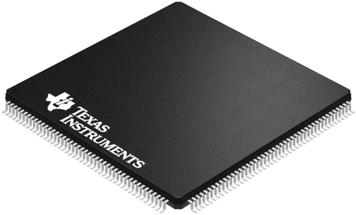
Images above are just a representation of the package family, actual package may vary. Refer to the product data sheet for package details.
4040134/C
TEXAS INSTRUMENTS

PACKAGE OUTLINE
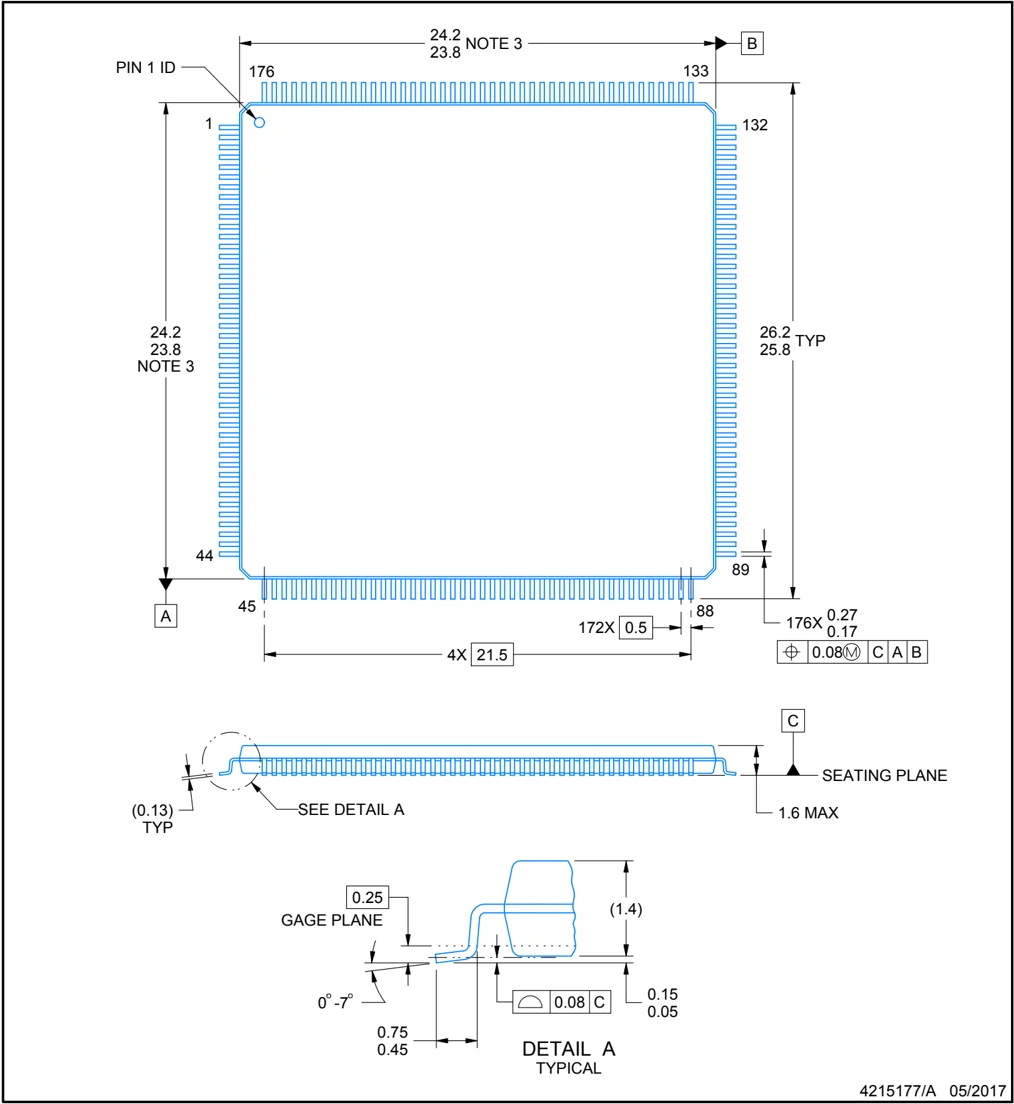
PGF0176A
LQFP - 1.6 mm max height
PLASTIC QUAD FLATPACK

NOTES:
- All linear dimensions are in millimeters. Any dimensions in parenthesis are for reference only. Dimensioning and tolerancing per ASME Y14.5M.
- This drawing is subject to change without notice.
- This dimension does not include mold flash, protrusions, or gate burrs.
- Reference JEDEC registration MS-026.
TEXAS INSTRUMENTS www.ti.com

EXAMPLE BOARD LAYOUT
PGF0176A
LQFP - 1.6 mm max height PLASTIC QUAD FLATPACK
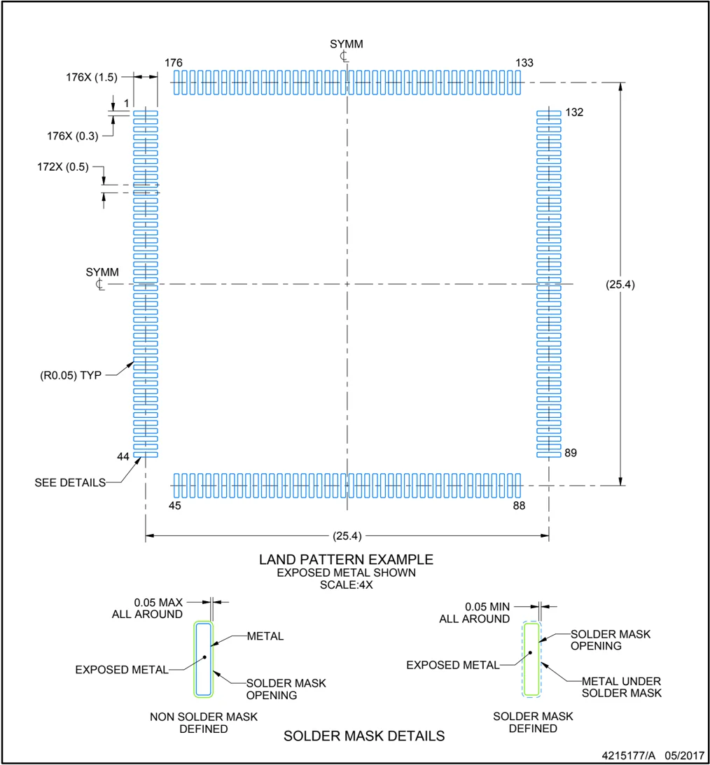
LAND PATTERN EXAMPLE EXPOSED METAL SHOWN SCALE:4X
SOLDER MASK DETAILS
4215177/A 05/2017
NOTES: (continued)
- Publication IPC-7351 may have alternate designs.
- Solder mask tolerances between and around signal pads can vary based on board fabrication site.

EXAMPLE STENCIL DESIGN
PGF0176A LQFP - 1.6 mm max height PLASTIC QUAD FLATPACK
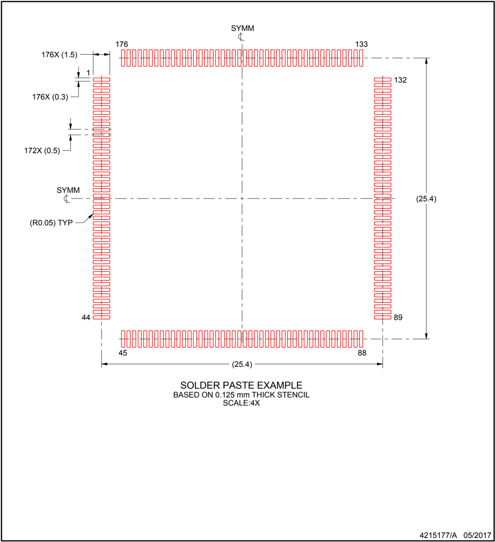
SYMM 176X (1.5) 176 133 1 176X (0.3) 132 172X (0.5) SYMM (R0.05) TYP (25.4) 44 89 45 88 (25.4)
SOLDER PASTE EXAMPLE BASED ON 0.125 mm THICK STENCIL SCALE:4X
4215177/A 05/2017
NOTES: (continued) 7. Laser cutting apertures with trapezoidal walls and rounded corners may offer better paste release. IPC-7525 may have alternate design recommendations. 8. Board assembly site may have different recommendations for stencil design.
TEXAS INSTRUMENTS www.ti.com

PACKAGE OUTLINE
GBB0179A NFBGA - 1.4 mm max height
PLASTIC BALL GRID ARRAY
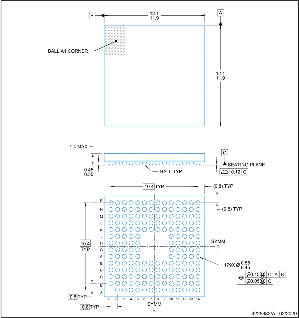
12.1 11.9 B A BALL A1 CORNER 12.1 11.9
1.4 MAX C SEATING PLANE 0.12 C 0.45 0.35 BALL TYP
10.4 TYP (0.8) TYP P N M L K J H G F E D C B A 10.4 TYP (0.8) TYP SYMM ℄ 179X Ø 0.55 0.45 ⊕ Ø0.15(M) C A B Ø0.05(M) C 0.8 TYP 0.8 TYP 1 2 3 4 5 6 7 8 9 10 11 12 13 14 SYMM ℄
4225682/A 02/2020
NOTES: NanoFree is a trademark of Texas Instruments.
- All linear dimensions are in millimeters. Any dimensions in parenthesis are for reference only. Dimensioning and tolerancing per ASME Y14.5M.
- This drawing is subject to change without notice.
TEXAS INSTRUMENTS www.ti.com

EXAMPLE BOARD LAYOUT
GBB0179A
NFBGA - 1.4 mm max height
PLASTIC BALL GRID ARRAY
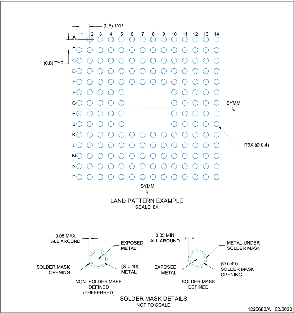
NOTES: (continued)
- Final dimensions may vary due to manufacturing tolerance considerations and also routing constraints. Refer to Texas Instruments Literature number SNVA009 (www.ti.com/lit/snva009).
4225682/A 02/2020

EXAMPLE STENCIL DESIGN
GBB0179A
NFBGA - 1.4 mm max height
PLASTIC BALL GRID ARRAY
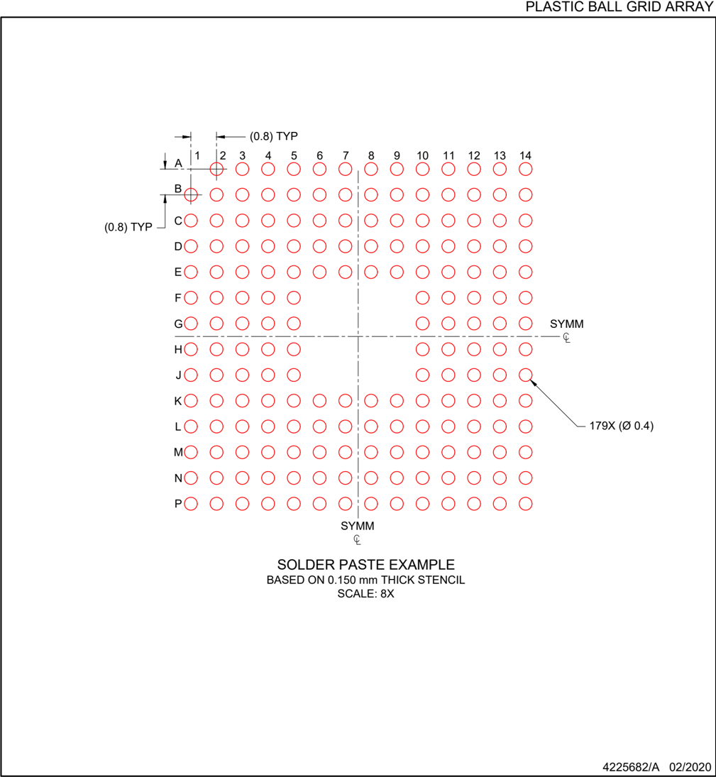
(0.8) TYP (0.8) TYP SYMM 179X (Ø 0.4) SYMM
SOLDER PASTE EXAMPLE BASED ON 0.150 mm THICK STENCIL SCALE: 8X
4225682/A 02/2020
NOTES: (continued) 4. Laser cutting apertures with trapezoidal walls and rounded corners may offer better paste release.
TEXAS INSTRUMENTS www.ti.com

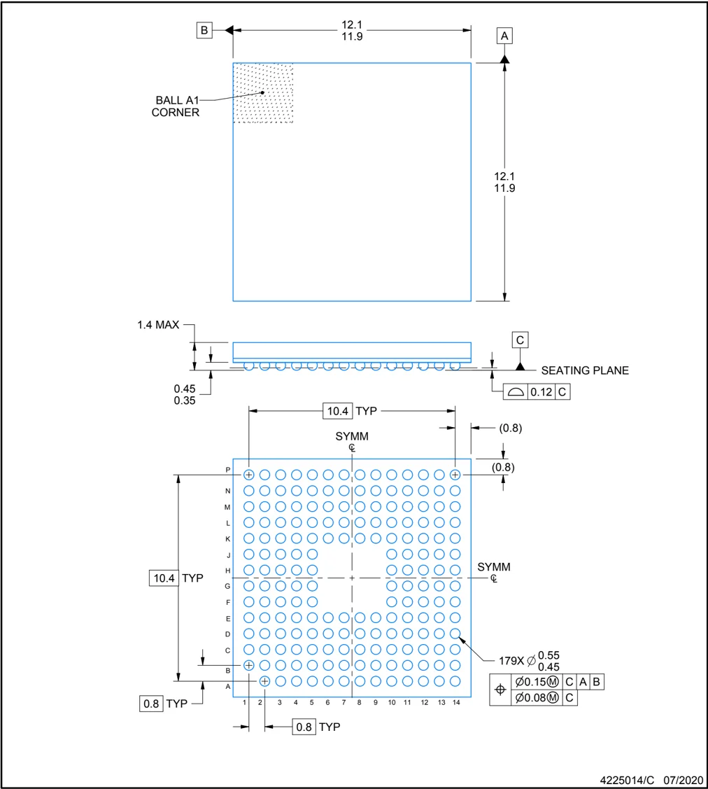
PACKAGE OUTLINE
ZAY0179A
NFBGA - 1.4 mm max height
PLASTIC BALL GRID ARRAY

B 12.1 11.9 A BALL A1 CORNER 12.1 11.9 1.4 MAX 0.45 0.35 C SEATING PLANE 0.12 C 10.4 TYP SYMM (0.8) (0.8) P N M L K J H G F E D C B A 10.4 TYP 0.8 TYP 1 2 3 4 5 6 7 8 9 10 11 12 13 14 0.8 TYP SYMM 179X Ø 0.55 0.45 Ø 0.15(M) C A B Ø 0.08(M) C
4225014/C 07/2020
NOTES:
- All linear dimensions are in millimeters. Any dimensions in parenthesis are for reference only. Dimensioning and tolerancing per ASME Y14.5M.
- This drawing is subject to change without notice.
TEXAS INSTRUMENTS www.ti.com

EXAMPLE BOARD LAYOUT
ZAY0179A NFBGA - 1.4 mm max height PLASTIC BALL GRID ARRAY
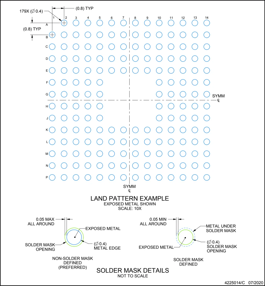
NOTES: (continued)
- Final dimensions may vary due to manufacturing tolerance considerations and also routing constraints. For information, see Texas Instruments literature number SPRAA99 (www.ti.com/lit/spraA99).
4225014/C 07/2020

EXAMPLE STENCIL DESIGN
ZAY0179A
NFBGA - 1.4 mm max height
PLASTIC BALL GRID ARRAY
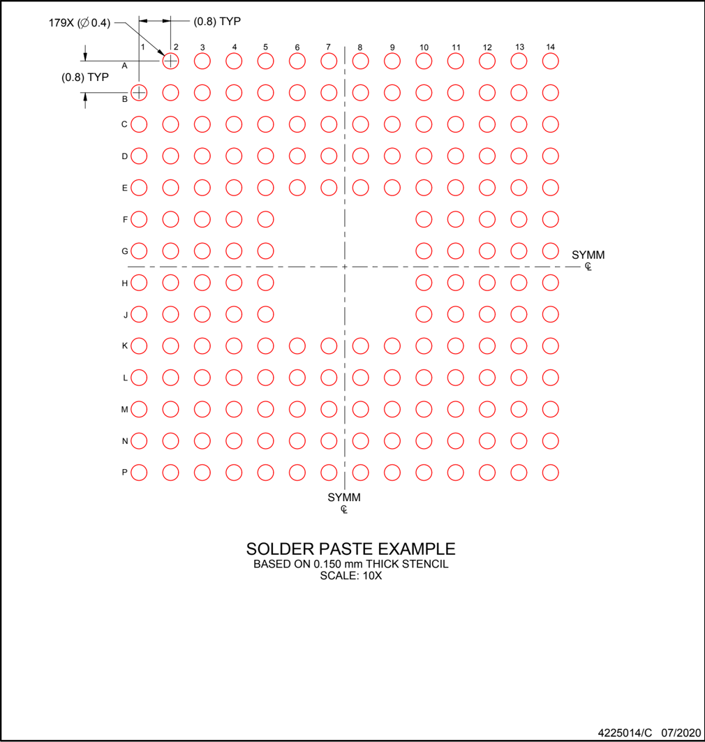
SOLDER PASTE EXAMPLE
BASED ON 0.150 mm THICK STENCIL
SCALE: 10X
4225014/C 07/2020
NOTES: (continued)
- Laser cutting apertures with trapezoidal walls and rounded corners may offer better paste release.
TEXAS INSTRUMENTS
www.ti.com

MECHANICAL DATA
PBK (S-PQFP-G128) PLASTIC QUAD FLATPACK
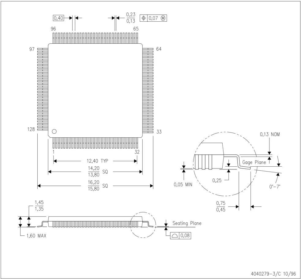
NOTES: A. All linear dimensions are in millimeters. B. This drawing is subject to change without notice. C. Falls within JEDEC MS-026
4040279-3/C 10/96
TEXAS INSTRUMENTS www.ti.com

LAND PATTERN DATA
PBK (S-PQFP-G128) PLASTIC QUAD FLAT PACK
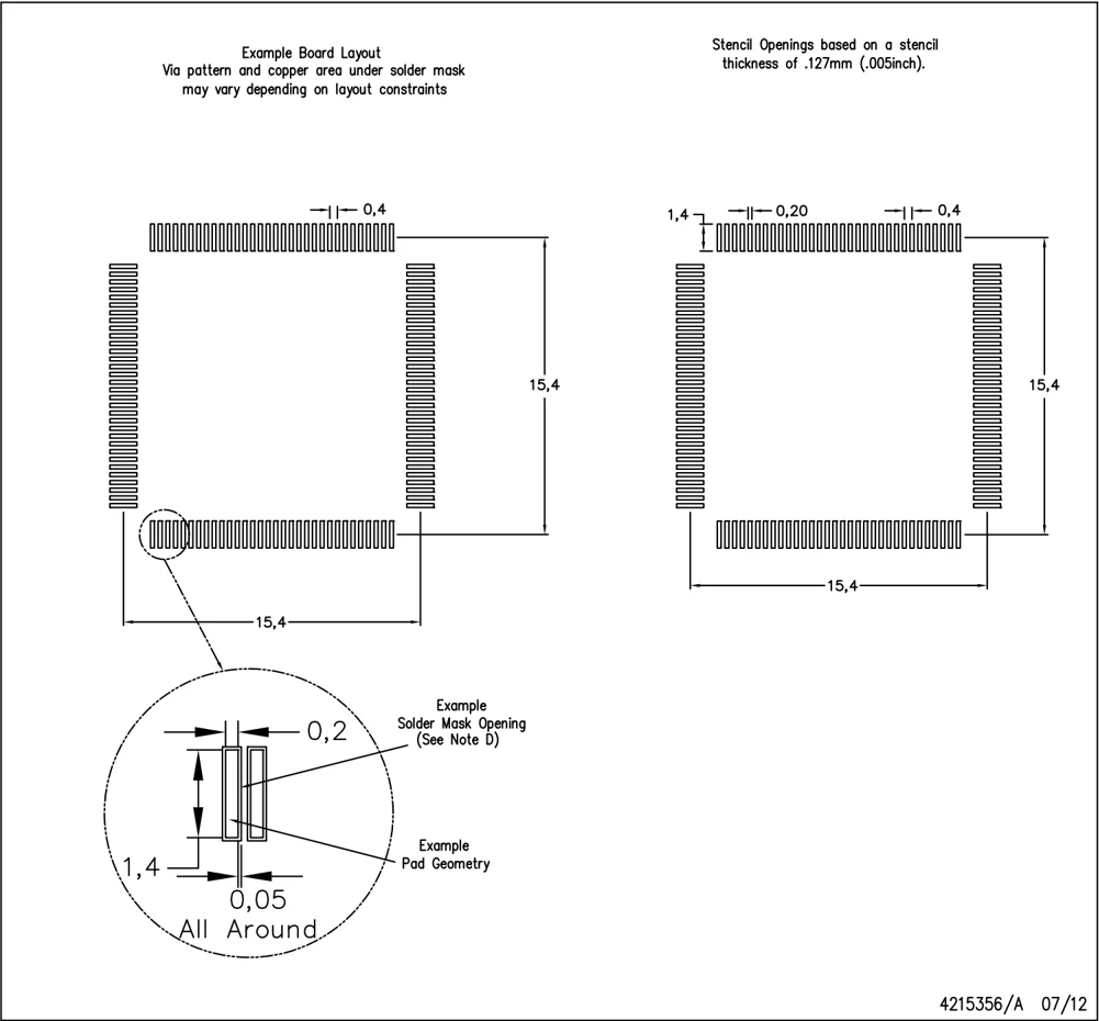
Example Board Layout Via pattern and copper area under solder mask may vary depending on layout constraints
0,4 15,4 15,4
Stencil Openings based on a stencil thickness of .127mm (.005inch).
1,4 0,20 0,4 15,4 15,4
Example Solder Mask Opening (See Note D) 0,2 Example Pad Geometry 1,4 0,05 All Around
4215356/A 07/12
NOTES: A. All linear dimensions are in millimeters. B. This drawing is subject to change without notice. C. Laser cutting apertures with trapezoidal walls and also rounding corners will offer better paste release. Customers should contact their board assembly site for stencil design recommendations. Example stencil metal load solder paste. Refer to IPC-7525 for other stencil recommendations. D. Customers should contact their board fabrication site for solder mask tolerances between and around signal pads.
TEXAS INSTRUMENTS www.ti.com

IMPORTANT NOTICE AND DISCLAIMER
TI PROVIDES TECHNICAL AND RELIABILITY DATA (INCLUDING DATASHEETS), DESIGN RESOURCES (INCLUDING REFERENCE DESIGNS), APPLICATION OR OTHER DESIGN ADVICE, WEB TOOLS, SAFETY INFORMATION, AND OTHER RESOURCES “AS IS” AND WITH ALL FAULTS, AND DISCLAIMS ALL WARRANTIES, EXPRESS AND IMPLIED, INCLUDING WITHOUT LIMITATION ANY IMPLIED WARRANTIES OF MERCHANTABILITY, FITNESS FOR A PARTICULAR PURPOSE OR NON-INFRINGEMENT OF THIRD PARTY INTELLECTUAL PROPERTY RIGHTS.
These resources are intended for skilled developers designing with TI products. You are solely responsible for (1) selecting the appropriate TI products for your application, (2) designing, validating and testing your application, and (3) ensuring your application meets applicable standards, and any other safety, security, regulatory or other requirements.
These resources are subject to change without notice. TI grants you permission to use these resources only for development of an application that uses the TI products described in the resource. Other reproduction and display of these resources is prohibited. No license is granted to any other TI intellectual property right or to any third party intellectual property right. TI disclaims responsibility for, and you fully indemnify TI and its representatives against any claims, damages, costs, losses, and liabilities arising out of your use of these resources.
TI’s products are provided subject to TI’s Terms of Sale, TI’s General Quality Guidelines, or other applicable terms available either on ti.com or provided in conjunction with such TI products. TI’s provision of these resources does not expand or otherwise alter TI’s applicable warranties or warranty disclaimers for TI products. Unless TI explicitly designates a product as custom or customer-specified, TI products are standard, catalog, general purpose devices.
TI objects to and rejects any additional or different terms you may propose.
Copyright © 2026, Texas Instruments Incorporated Last updated 10/2025