MICROCHIP
PIC32MX3XX/4XX
Data Sheet
High-Performance, General Purpose and USB, 32-bit Flash Microcontrollers
© 2011 Microchip Technology Inc. DS61143H

Note the following details of the code protection feature on Microchip devices:
- Microchip products meet the specification contained in their particular Microchip Data Sheet.
- Microchip believes that its family of products is one of the most secure families of its kind on the market today, when used in the intended manner and under normal conditions.
- There are dishonest and possibly illegal methods used to breach the code protection feature. All of these methods, to our knowledge, require using the Microchip products in a manner outside the operating specifications contained in Microchip’s Data Sheets. Most likely, the person doing so is engaged in theft of intellectual property.
- Microchip is willing to work with the customer who is concerned about the integrity of their code.
- Neither Microchip nor any other semiconductor manufacturer can guarantee the security of their code. Code protection does not mean that we are guaranteeing the product as “unbreakable.”
Code protection is constantly evolving. We at Microchip are committed to continuously improving the code protection features of our products. Attempts to break Microchip’s code protection feature may be a violation of the Digital Millennium Copyright Act. If such acts allow unauthorized access to your software or other copyrighted work, you may have a right to sue for relief under that Act.
Information contained in this publication regarding device applications and the like is provided only for your convenience and may be superseded by updates. It is your responsibility to ensure that your application meets with your specifications. MICROCHIP MAKES NO REPRESENTATIONS OR WARRANTIES OF ANY KIND WHETHER EXPRESS OR IMPLIED, WRITTEN OR ORAL, STATUTORY OR OTHERWISE, RELATED TO THE INFORMATION, INCLUDING BUT NOT LIMITED TO ITS CONDITION, QUALITY, PERFORMANCE, MERCHANTABILITY OR FITNESS FOR PURPOSE. Microchip disclaims all liability arising from this information and its use. Use of Microchip devices in life support and/or safety applications is entirely at the buyer’s risk, and the buyer agrees to defend, indemnify and hold harmless Microchip from any and all damages, claims, suits, or expenses resulting from such use. No licenses are conveyed, implicitly or otherwise, under any Microchip intellectual property rights.
Trademarks
The Microchip name and logo, the Microchip logo, dsPIC, KEELOQ, KEELOQ logo, MPLAB, PIC, PICmicro, PICSTART, PIC$^{32}$ logo, rfPIC and UNI/O are registered trademarks of Microchip Technology Incorporated in the U.S.A. and other countries.
FilterLab, Hampshire, HI-TECH C, Linear Active Thermistor, MXDEV, MXLAB, SEEVAL and The Embedded Control Solutions Company are registered trademarks of Microchip Technology Incorporated in the U.S.A.
Analog-for-the-Digital Age, Application Maestro, CodeGuard, dsPICDEM, dsPICDEM.net, dsPICworks, dsSPEAK, ECAN, ECONOMONITOR, FanSense, HI-TIDE, In-Circuit Serial Programming, ICSP, Mindi, MiWi, MPASM, MPLAB Certified logo, MPLIB, MPLINK, mTouch, Omniscient Code Generation, PICC, PICC-18, PICDEM, PICDEM.net, PICKit, PICtail, REAL ICE, rfLAB, Select Mode, Total Endurance, TSHARC, UniWinDriver, WiperLock and ZENA are trademarks of Microchip Technology Incorporated in the U.S.A. and other countries.
SQTP is a service mark of Microchip Technology Incorporated in the U.S.A.
All other trademarks mentioned herein are property of their respective companies.
© 2011, Microchip Technology Incorporated, Printed in the U.S.A., All Rights Reserved.
Printed on recycled paper.
ISBN: 978-1-61341-149-0
Microchip received ISO/TS-16949:2002 certification for its worldwide headquarters, design and wafer fabrication facilities in Chandler and Tempe, Arizona; Gresham, Oregon and design centers in California and India. The Company’s quality system processes and procedures are for its PIC® MCUs and dsPIC® DSCs, KEELOQ® code hopping devices, Serial EEPROMs, microperipherals, nonvolatile memory and analog products. In addition, Microchip’s quality system for the design and manufacture of development systems is ISO 9001:2000 certified.
QUALITY MANAGEMENT SYSTEM CERTIFIED BY DNV =ISO/TS 16949:2002=
High-Performance, General Purpose and USB 32-bit Flash Microcontrollers
High-Performance 32-bit RISC CPU:
- MIPS32® M4K® 32-bit core with 5-stage pipeline
- 80 MHz maximum frequency
- 1.56 DMIPS/MHz (Dhrystone 2.1) performance at 0 wait state Flash access
- Single-cycle multiply and high-performance divide unit
- MIPS16e® mode for up to 40% smaller code size
- Two sets of 32 core register files (32-bit) to reduce interrupt latency
- Prefetch Cache module to speed execution from Flash
Microcontroller Features:
- Operating temperature range of -40°C to +105°C
- Operating voltage range of 2.3V to 3.6V
- 32K to 512K Flash memory (plus an additional 12 KB of boot Flash)
- 8K to 32K SRAM memory
- Pin-compatible with most PIC24/dsPIC® DSC devices
- Multiple power management modes
- Multiple interrupt vectors with individually programmable priority
- Fail-Safe Clock Monitor Mode
- Configurable Watchdog Timer with on-chip Low-Power RC Oscillator for reliable operation
Peripheral Features:
-
Atomic SET, CLEAR and INVERT operation on select peripheral registers
-
Up to 4-channel hardware DMA with automatic data size detection
-
USB 2.0-compliant full-speed device and On-The-Go (OTG) controller
-
USB has a dedicated DMA channel
-
3 MHz to 25 MHz crystal oscillator
-
Internal 8 MHz and 32 kHz oscillators
-
Separate PLLs for CPU and USB clocks
-
Two I²C™ modules
-
Two UART modules with:
- RS-232, RS-485 and LIN support
- IrDA® with on-chip hardware encoder and decoder
-
Up to two SPI modules
-
Parallel Master and Slave Port (PMP/PSP) with 8-bit and 16-bit data and up to 16 address lines
-
Hardware Real-Time Clock and Calendar (RTCC)
-
Five 16-bit Timers/Counters (two 16-bit pairs combine to create two 32-bit timers)
-
Five capture inputs
-
Five compare/PWM outputs
-
Five external interrupt pins
-
High-Speed I/O pins capable of toggling at up to 80 MHz
-
High-current sink/source (18 mA/18 mA) on all I/O pins
-
Configurable open-drain output on digital I/O pins
Debug Features:
- Two programming and debugging Interfaces:
- 2-wire interface with unintrusive access and real-time data exchange with application
- 4-wire MIPS® standard enhanced JTAG interface
- Unintrusive hardware-based instruction trace
- IEEE Standard 1149.2-compatible (JTAG) boundary scan
Analog Features:
- Up to 16-channel 10-bit Analog-to-Digital Converter:
- 1000 ksps conversion rate
- Conversion available during Sleep, Idle
- Two Analog Comparators

TABLE 1: PIC32MX GENERAL PURPOSE – FEATURES
\begin{tabular}{|l|c|c|c|c|c|c|c|c|c|c|c|c|c|} \hline \multicolumn{13}{|c|}{GENERAL PURPOSE} \ \hline \textbf{Device} & \textbf{Pins} & \textbf{Packages$^{(2)}$} & \textbf{MHz} & \textbf{Program Memory (KB)} & \textbf{Data Memory (KB)} & \textbf{Timers/Capture/Compare} & \textbf{Programmable DMA Channels} & \textbf{VREG} & \textbf{Trace} & \textbf{EUART/SPI/I$^2$C^TM} & \textbf{10-bit ADC (ch)} & \textbf{Comparators} & \textbf{PMP/PSP} & \textbf{JTAG} \ \hline PIC32MX320F032H & 64 & PT, MR & 40 & 32 + 12$^{(1)}$ & 8 & 5/5/5 & 0 & Yes & No & 2/2/2 & 16 & 2 & Yes & Yes \ \hline PIC32MX320F064H & 64 & PT, MR & 80 & 64 + 12$^{(1)}$ & 16 & 5/5/5 & 0 & Yes & No & 2/2/2 & 16 & 2 & Yes & Yes \ \hline PIC32MX320F128H & 64 & PT, MR & 80 & 128 + 12$^{(1)}$ & 16 & 5/5/5 & 0 & Yes & No & 2/2/2 & 16 & 2 & Yes & Yes \ \hline PIC32MX340F128H & 64 & PT, MR & 80 & 128 + 12$^{(1)}$ & 32 & 5/5/5 & 4 & Yes & No & 2/2/2 & 16 & 2 & Yes & Yes \ \hline PIC32MX340F256H & 64 & PT, MR & 80 & 256 + 12$^{(1)}$ & 32 & 5/5/5 & 4 & Yes & No & 2/2/2 & 16 & 2 & Yes & Yes \ \hline PIC32MX340F512H & 64 & PT, MR & 80 & 512 + 12$^{(1)}$ & 32 & 5/5/5 & 4 & Yes & No & 2/2/2 & 16 & 2 & Yes & Yes \ \hline \multirow{2}{}{PIC32MX320F128L} & 100 & PT & \multirow{2}{}{80} & \multirow{2}{}{128 + 12$^{(1)}$} & \multirow{2}{}{16} & \multirow{2}{}{5/5/5} & \multirow{2}{}{0} & \multirow{2}{}{Yes} & \multirow{2}{}{No} & \multirow{2}{}{2/2/2} & \multirow{2}{}{16} & \multirow{2}{}{2} & \multirow{2}{}{Yes} & \multirow{2}{}{Yes} \ \cline{2-3} & 121 & BG & & & & & & & & & & & & \ \hline \multirow{2}{}{PIC32MX340F128L} & 100 & PT & \multirow{2}{}{80} & \multirow{2}{}{128 + 12$^{(1)}$} & \multirow{2}{}{32} & \multirow{2}{}{5/5/5} & \multirow{2}{}{4} & \multirow{2}{}{Yes} & \multirow{2}{}{No} & \multirow{2}{}{2/2/2} & \multirow{2}{}{16} & \multirow{2}{}{2} & \multirow{2}{}{Yes} & \multirow{2}{}{Yes} \ \cline{2-3} & 121 & BG & & & & & & & & & & & & \ \hline \multirow{2}{}{PIC32MX360F256L} & 100 & PT & \multirow{2}{}{80} & \multirow{2}{}{256 + 12$^{(1)}$} & \multirow{2}{}{32} & \multirow{2}{}{5/5/5} & \multirow{2}{}{4} & \multirow{2}{}{Yes} & \multirow{2}{}{Yes} & \multirow{2}{}{2/2/2} & \multirow{2}{}{16} & \multirow{2}{}{2} & \multirow{2}{}{Yes} & \multirow{2}{}{Yes} \ \cline{2-3} & 121 & BG & & & & & & & & & & & & \ \hline \multirow{2}{}{PIC32MX360F512L} & 100 & PT & \multirow{2}{}{80} & \multirow{2}{}{512 + 12$^{(1)}$} & \multirow{2}{}{32} & \multirow{2}{}{5/5/5} & \multirow{2}{}{4} & \multirow{2}{}{Yes} & \multirow{2}{}{Yes} & \multirow{2}{}{2/2/2} & \multirow{2}{}{16} & \multirow{2}{}{2} & \multirow{2}{}{Yes} & \multirow{2}{}{Yes} \ \cline{2-3} & 121 & BG & & & & & & & & & & & & \ \hline \end{tabular}
Legend: PT = TQFP MR = QFN BG = XBGA Note 1: This device features 12 KB Boot Flash memory. 2: See Legend for an explanation of the acronyms. See Section 30.0 "Packaging Information" for details.
DS61143H-page 4 © 2011 Microchip Technology Inc.
TABLE 2: PIC32MX USB – FEATURES
\begin{tabular}{|l|c|c|c|c|c|c|c|c|c|c|c|c|c|c|} \hline \multicolumn{15}{|c|}{USB} \ \hline \textbf{Device} & \textbf{Pins} & \textbf{Packages$^{(2)}$} & \textbf{MHz} & \textbf{Program Memory (KB)} & \textbf{Data Memory (KB)} & \textbf{Timers/Capture/Compare} & \textbf{Programmable DMA Channels} & \textbf{Dedicated USB DMA Channels} & \textbf{VREG} & \textbf{Trace} & \textbf{EUART/SPI/I$^2$C^TM} & \textbf{10-bit ADC (ch)} & \textbf{Comparators} & \textbf{PMP/PSP} & \textbf{JTAG} \ \hline PIC32MX420F032H & 64 & PT, MR & 40 & 32 + 12$^{(1)}$ & 8 & 5/5/5 & 0 & 2 & Yes & No & 2/1/2 & 16 & 2 & Yes & Yes \ \hline PIC32MX440F128H & 64 & PT, MR & 80 & 128 + 12$^{(1)}$ & 32 & 5/5/5 & 4 & 2 & Yes & No & 2/1/2 & 16 & 2 & Yes & Yes \ \hline PIC32MX440F256H & 64 & PT, MR & 80 & 256 + 12$^{(1)}$ & 32 & 5/5/5 & 4 & 2 & Yes & No & 2/1/2 & 16 & 2 & Yes & Yes \ \hline PIC32MX440F512H & 64 & PT, MR & 80 & 512 + 12$^{(1)}$ & 32 & 5/5/5 & 4 & 2 & Yes & No & 2/1/2 & 16 & 2 & Yes & Yes \ \hline \multirow{2}{}{PIC32MX440F128L} & 100 & PT & \multirow{2}{}{80} & \multirow{2}{}{128 + 12$^{(1)}$} & \multirow{2}{}{32} & \multirow{2}{}{5/5/5} & \multirow{2}{}{4} & \multirow{2}{}{2} & \multirow{2}{}{Yes} & \multirow{2}{}{No} & \multirow{2}{}{2/2/2} & \multirow{2}{}{16} & \multirow{2}{}{2} & \multirow{2}{}{Yes} & \multirow{2}{}{Yes} \ \cline{2-3} & 121 & BG & & & & & & & & & & & & & \ \hline \multirow{2}{}{PIC32MX460F256L} & 100 & PT & \multirow{2}{}{80} & \multirow{2}{}{256 + 12$^{(1)}$} & \multirow{2}{}{32} & \multirow{2}{}{5/5/5} & \multirow{2}{}{4} & \multirow{2}{}{2} & \multirow{2}{}{Yes} & \multirow{2}{}{Yes} & \multirow{2}{}{2/2/2} & \multirow{2}{}{16} & \multirow{2}{}{2} & \multirow{2}{}{Yes} & \multirow{2}{}{Yes} \ \cline{2-3} & 121 & BG & & & & & & & & & & & & & \ \hline \multirow{2}{}{PIC32MX460F512L} & 100 & PT & \multirow{2}{}{80} & \multirow{2}{}{512 + 12$^{(1)}$} & \multirow{2}{}{32} & \multirow{2}{}{5/5/5} & \multirow{2}{}{4} & \multirow{2}{}{2} & \multirow{2}{}{Yes} & \multirow{2}{}{Yes} & \multirow{2}{}{2/2/2} & \multirow{2}{}{16} & \multirow{2}{}{2} & \multirow{2}{}{Yes} & \multirow{2}{}{Yes} \ \cline{2-3} & 121 & BG & & & & & & & & & & & & & \ \hline \end{tabular}
Legend: PT = TQFP MR = QFN BG = XBGA Note 1: This device features 12 KB Boot Flash memory. 2: See Legend for an explanation of the acronyms. See Section 30.0 “Packaging Information” for details.
Pin Diagrams
64-Pin QFN (General Purpose)
■ = Pins are up to 5V tolerant
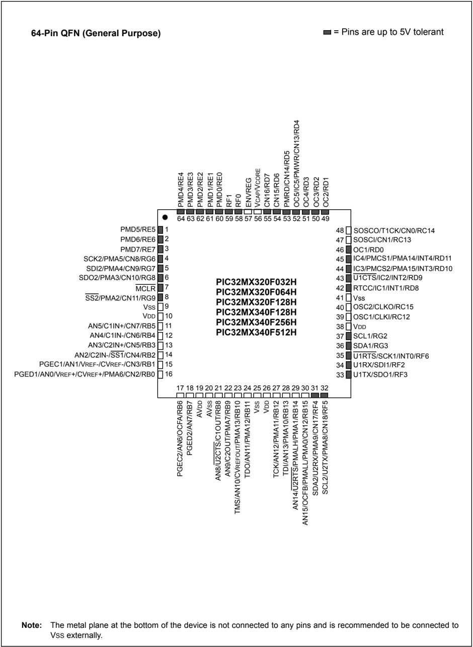
Note: The metal plane at the bottom of the device is not connected to any pins and is recommended to be connected to Vss externally.
Pin Diagrams (Continued)
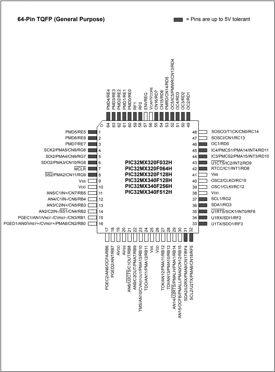
64-Pin TQFP (General Purpose)
Pin Diagrams (Continued)
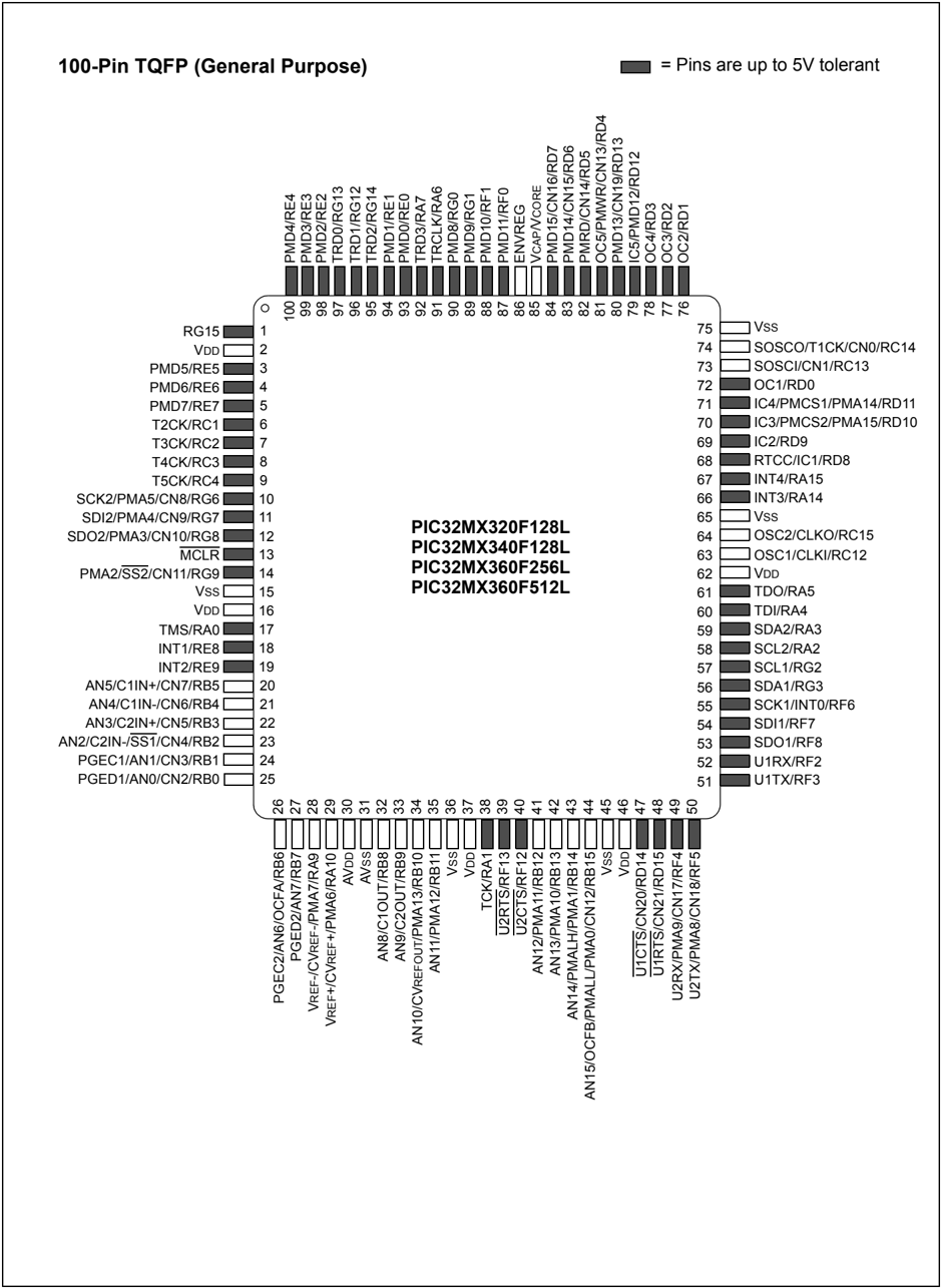
100-Pin TQFP (General Purpose)
= Pins are up to 5V tolerant
Pin Diagrams (Continued)
121-Pin XBGA⁽¹⁾
PIC32MX320F128L
PIC32MX340F128L
PIC32MX360F256L
PIC32MX360F512L
● = Pins are up to 5V tolerant
| 1 | 2 | 3 | 4 | 5 | 6 | 7 | 8 | 9 | 10 | 11 | |
|---|---|---|---|---|---|---|---|---|---|---|---|
| A | RE4 | RE3 | RG13 | RE0 | RG0 | RF1 | ENVREG | Vss | RD12 | RD2 | RD1 |
| B | NC | RG15 | RE2 | RE1 | RA7 | RF0 | VCORE/ | RD5 | RD3 | Vss | RC14 |
| VCAP | |||||||||||
| C | RE6 | VDD | RG12 | RG14 | RA6 | NC | RD7 | RD4 | VDD | RC13 | RD11 |
| D | RC1 | RE7 | RE5 | Vss | Vss | NC | RD6 | RD13 | RD0 | NC | RD10 |
| E | RC4 | RC3 | RG6 | RC2 | VDD | RG1 | Vss | RA15 | RD8 | RD9 | RA14 |
| F | MCLR | RG8 | RG9 | RG7 | Vss | NC | NC | VDD | RC12 | Vss | RC15 |
| G | RE8 | RE9 | RA0 | NC | VDD | Vss | Vss | NC | RA5 | RA3 | RA4 |
| H | RB5 | RB4 | Vss | VDD | NC | VDD | NC | RF7 | RF6 | RG2 | RA2 |
| J | RB3 | RB2 | RB7 | AVDD | RB11 | RA1 | RB12 | NC | NC | RF8 | RG3 |
| K | RB1 | RB0 | RA10 | RB8 | NC | RF12 | RB14 | VDD | RD15 | RF3 | RF2 |
| L | RB6 | RA9 | AVss | RB9 | RB10 | RF13 | RB13 | RB15 | RD14 | RF4 | RF5 |
Note 1: Refer to Table 3 for full pin names.
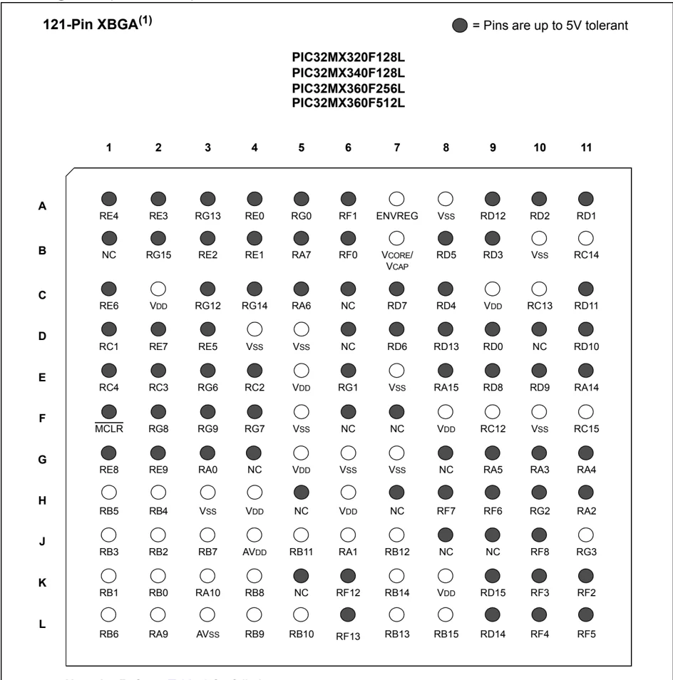
TABLE 3: PIN NAMES: PIC32MX320F128L, PIC32MX340F128L, PIC32MX360F128L, AND PIC32MX360F512L DEVICES
| Pin Number | Full Pin Name |
|---|---|
| A1 | PMD4/RE4 |
| A2 | PMD3/RE3 |
| A3 | TRD0/RG13 |
| A4 | PMD0/RE0 |
| A5 | PMD8/RG0 |
| A6 | PMD10/RF1 |
| A7 | ENVREG |
| A8 | Vss |
| A9 | IC5/PMD12/RD12 |
| A10 | OC3/RD2 |
| A11 | OC2/RD1 |
| B1 | No Connect (NC) |
| B2 | RG15 |
| B3 | PMD2/RE2 |
| B4 | PMD1/RE1 |
| B5 | TRD3/RA7 |
| B6 | PMD11/RF0 |
| B7 | VCAP/VCORE |
| B8 | PMRD/CN14/RD5 |
| B9 | OC4/RD3 |
| B10 | Vss |
| B11 | SOSCO/T1CK/CN0/RC14 |
| C1 | PMD6/RE6 |
| C2 | VDD |
| C3 | TRD1/RG12 |
| C4 | TRD2/RG14 |
| C5 | TRCLK/RA6 |
| C6 | No Connect (NC) |
| C7 | PMD15/CN16/RD7 |
| C8 | OC5/PMWR/CN13/RD4 |
| C9 | VDD |
| C10 | SOSCI/CN1/RC13 |
| C11 | IC4/PMCS1/PMA14/RD11 |
| D1 | T2CK/RC1 |
| D2 | PMD7/RE7 |
| D3 | PMD5/RE5 |
| D4 | Vss |
| D5 | Vss |
| D6 | No Connect (NC) |
| D7 | PMD14/CN15/RD6 |
| D8 | PMD13/CN19/RD13 |
| D9 | OC1/RD0 |
| D10 | No Connect (NC) |
| D11 | IC3/PMCS2/PMA15/RD10 |
| E1 | T5CK/RC4 |
| E2 | T4CK/RC3 |
| E3 | SCK2/PMA5/CN8/RG6 |
| E4 | T3CK/RC2 |
| E5 | VDD |
| E6 | PMD9/RG1 |
| E7 | Vss |
| Pin Number | Full Pin Name |
|---|---|
| E8 | INT4/RA15 |
| E9 | RTCC/IC1/RD8 |
| E10 | IC2/RD9 |
| E11 | INT3/RA14 |
| F1 | MCLR |
| F2 | SDO2/PMA3/CN10/RG8 |
| F3 | SS2/PMA2/CN11/RG9 |
| F4 | SDI2/PMA4/CN9/RG7 |
| F5 | Vss |
| F6 | No Connect (NC) |
| F7 | No Connect (NC) |
| F8 | VDD |
| F9 | OSC1/CLKI/RC12 |
| F10 | Vss |
| F11 | OSC2/CLKO/RC15 |
| G1 | INT1/RE8 |
| G2 | INT2/RE9 |
| G3 | TMS/RA0 |
| G4 | No Connect (NC) |
| G5 | VDD |
| G6 | Vss |
| G7 | Vss |
| G8 | No Connect (NC) |
| G9 | TDO/RA5 |
| G10 | SDA2/RA3 |
| G11 | TDI/RA4 |
| H1 | AN5/C1IN+/CN7/RB5 |
| H2 | AN4/C1IN-/CN6/RB4 |
| H3 | Vss |
| H4 | VDD |
| H5 | No Connect (NC) |
| H6 | VDD |
| H7 | No Connect (NC) |
| H8 | SDI1/RF7 |
| H9 | SCK1/INT0/RF6 |
| H10 | SCL1/RG2 |
| H11 | SCL2/RA2 |
| J1 | AN3/C2IN+/CN5/RB3 |
| J2 | AN2/C2IN-/SS1/CN4/RB2 |
| J3 | PGED2/AN7/RB7 |
| J4 | AVDD |
| J5 | AN11/PMA12/RB11 |
| J6 | TCK/RA1 |
| J7 | AN12/PMA11/RB12 |
| J8 | No Connect (NC) |
| J9 | No Connect (NC) |
| J10 | SDO1/RF8 |
| J11 | SDA1/RG3 |
| K1 | PGEC1/AN1/CN3/RB1 |
| K2 | PGED1/AN0/CN2/RB0 |
| K3 | VREF+/CVREF+/PMA6/RA10 |
TABLE 3: PIN NAMES: PIC32MX320F128L, PIC32MX340F128L, PIC32MX360F128L, AND PIC32MX360F512L DEVICES (CONTINUED)
| Pin Number | Full Pin Name |
|---|---|
| K4 | AN8/C1OUT/RB8 |
| K5 | No Connect (NC) |
| K6 | U2CTS/RF12 |
| K7 | AN14/PMALH/PMA1/RB14 |
| K8 | VDD |
| K9 | U1RTS/CN21/RD15 |
| K10 | U1TX/RF3 |
| K11 | U1RX/RF2 |
| L1 | PGEC2/AN6/OCFA/RB6 |
| L2 | VREF-/CVREF-/PMA7/RA9 |
| Pin Number | Full Pin Name |
|---|---|
| L3 | AVss |
| L4 | AN9/C2OUT/RB9 |
| L5 | AN10/CVREFOUT/PMA13/RB10 |
| L6 | U2RTS/RF13 |
| L7 | AN13/PMA10/RB13 |
| L8 | AN15/OCFB/PMALL/PMA0/CN12/RB15 |
| L9 | CN20/U1CTS/RD14 |
| L10 | U2RX/PMA9/CN17/RF4 |
| L11 | U2TX/PMA8/CN18/RF5 |
Pin Diagrams (Continued)
64-Pin QFN (USB)
■ = Pins are up to 5V tolerant
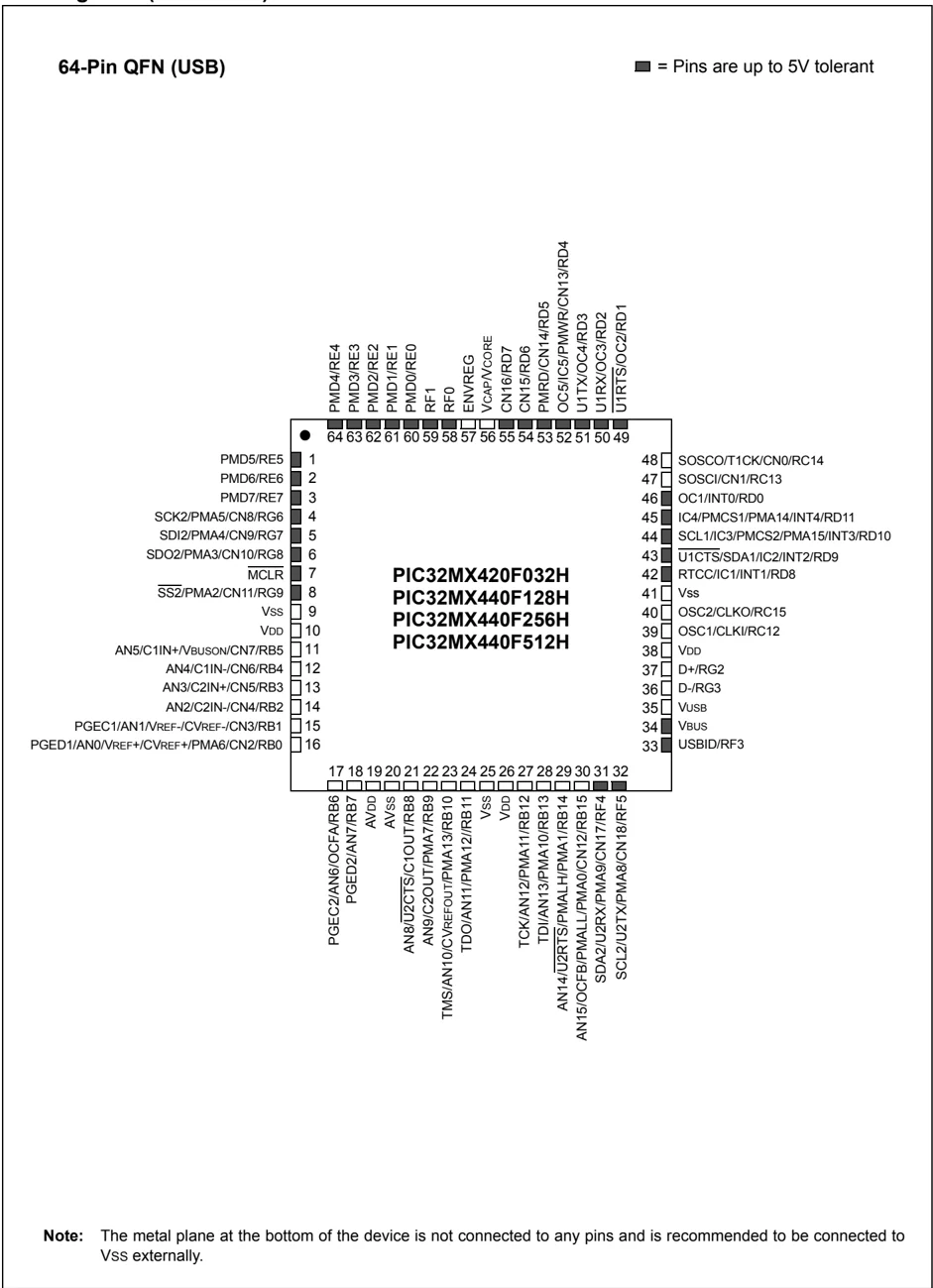
Note: The metal plane at the bottom of the device is not connected to any pins and is recommended to be connected to Vss externally.
Pin Diagrams (Continued)
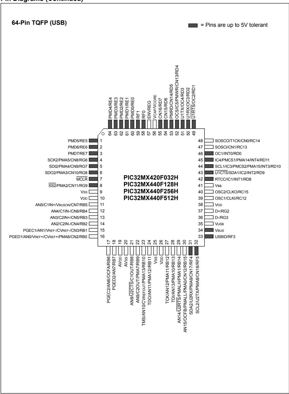
64-Pin TQFP (USB)
© 2011 Microchip Technology Inc. DS61143H-page 13
Pin Diagrams (Continued)
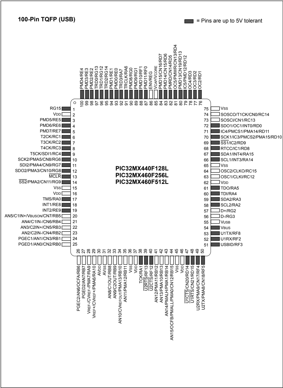
100-Pin TQFP (USB)
Pin Diagrams (Continued)
121-Pin XBGA(1)
PIC32MX440F128L
PIC32MX460F256L
PIC32MX460F512L
● = Pins are up to 5V tolerant
| 1 | 2 | 3 | 4 | 5 | 6 | 7 | 8 | 9 | 10 | 11 | |
|---|---|---|---|---|---|---|---|---|---|---|---|
| A | RE4 | RE3 | RG13 | RE0 | RG0 | RF1 | ENVREG | Vss | RD12 | RD2 | RD1 |
| B | NC | RG15 | RE2 | RE1 | RA7 | RF0 | VCORE/VCAP | RD5 | RD3 | Vss | RC14 |
| C | RE6 | VDD | RG12 | RG14 | RA6 | NC | RD7 | RD4 | VDD | RC13 | RD11 |
| D | RC1 | RE7 | RE5 | Vss | Vss | NC | RD6 | RD13 | RD0 | NC | RD10 |
| E | RC4 | RC3 | RG6 | RC2 | VDD | RG1 | Vss | RA15 | RD8 | RD9 | RA14 |
| F | MCLR | RG8 | RG9 | RG7 | Vss | NC | NC | VDD | RC12 | Vss | RC15 |
| G | RE8 | RE9 | RA0 | NC | VDD | Vss | Vss | NC | RA5 | RA3 | RA4 |
| H | RB5 | RB4 | Vss | VDD | NC | VDD | NC | VBUS | VUSB | RG2 | RA2 |
| J | RB3 | RB2 | RB7 | AVDD | RB11 | RA1 | RB12 | NC | NC | RF8 | RG3 |
| K | RB1 | RB0 | RA10 | RB8 | NC | RF12 | RB14 | VDD | RD15 | RF3 | RF2 |
| L | RB6 | RA9 | AVss | RB9 | RB10 | RF13 | RB13 | RB15 | RD14 | RF4 | RF5 |
Note 1: Refer to Table 4 for full pin names.
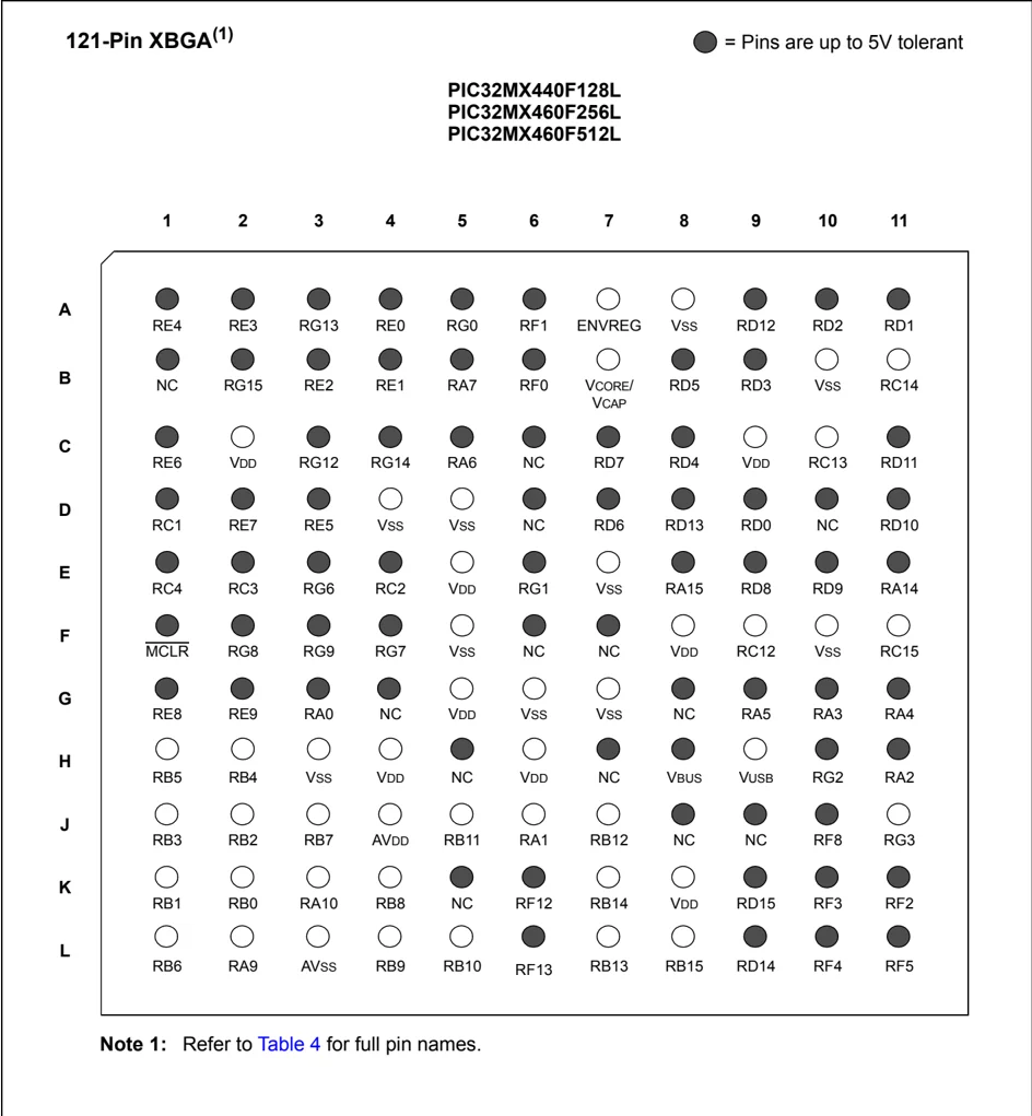
TABLE 4: PIN NAMES: PIC32MX440F128L, PIC32MX460F256L AND PIC32MX460F512L DEVICES
| Pin Number | Full Pin Name |
|---|---|
| A1 | PMD4/RE4 |
| A2 | PMD3/RE3 |
| A3 | TRD0/RG13 |
| A4 | PMD0/RE0 |
| A5 | PMD8/RG0 |
| A6 | PMD10/RF1 |
| A7 | ENVREG |
| A8 | Vss |
| A9 | IC5/PMD12/RD12 |
| A10 | OC3/RD2 |
| A11 | OC2/RD1 |
| B1 | No Connect (NC) |
| B2 | RG15 |
| B3 | PMD2/RE2 |
| B4 | PMD1/RE1 |
| B5 | TRD3/RA7 |
| B6 | PMD11/RF0 |
| B7 | VCAP/VCORE |
| B8 | PMRD/CN14/RD5 |
| B9 | OC4/RD3 |
| B10 | Vss |
| B11 | SOSCO/T1CK/CN0/RC14 |
| C1 | PMD6/RE6 |
| C2 | VDD |
| C3 | TRD1/RG12 |
| C4 | TRD2/RG14 |
| C5 | TRCLK/RA6 |
| C6 | No Connect (NC) |
| C7 | PMD15/CN16/RD7 |
| C8 | OC5/PMWR/CN13/RD4 |
| C9 | VDD |
| C10 | SOSCI/CN1/RC13 |
| C11 | IC4/PMCS1/PMA14/RD11 |
| D1 | T2CK/RC1 |
| D2 | PMD7/RE7 |
| D3 | PMD5/RE5 |
| D4 | Vss |
| D5 | Vss |
| D6 | No Connect (NC) |
| D7 | PMD14/CN15/RD6 |
| D8 | CN19/PMD13/RD13 |
| D9 | SDO1/OC1/INT0/RD0 |
| D10 | No Connect (NC) |
| D11 | SCK1/IC3/PMCS2/PMA15/RD10 |
| E1 | T5CK/SDI1/RC4 |
| E2 | T4CK/RC3 |
| E3 | SCK2/PMA5/CN8/RG6 |
| E4 | T3CK/RC2 |
| E5 | VDD |
| E6 | PMD9/RG1 |
| E7 | Vss |
| Pin Number | Full Pin Name |
|---|---|
| E8 | SDA1/INT4/RA15 |
| E9 | RTCC/IC1/RD8 |
| E10 | SS1/IC2/RD9 |
| E11 | SCL1/INT3/RA14 |
| F1 | MCLR |
| F2 | SDO2/PMA3/CN10/RG8 |
| F3 | SS2/PMA2/CN11/RG9 |
| F4 | SDI2/PMA4/CN9/RG7 |
| F5 | Vss |
| F6 | No Connect (NC) |
| F7 | No Connect (NC) |
| F8 | Vdd |
| F9 | OSC1/CLKI/RC12 |
| F10 | Vss |
| F11 | OSC2/CLKO/RC15 |
| G1 | INT1/RE8 |
| G2 | INT2/RE9 |
| G3 | TMS/RA0 |
| G4 | No Connect (NC) |
| G5 | VDD |
| G6 | Vss |
| G7 | Vss |
| G8 | No Connect (NC) |
| G9 | TDO/RA5 |
| G10 | SDA2/RA3 |
| G11 | TDI/RA4 |
| H1 | AN5/C1IN+/VBUSON/CN7/RB5 |
| H2 | AN4/C1IN-/CN6/RB4 |
| H3 | Vss |
| H4 | VDD |
| H5 | No Connect (NC) |
| H6 | VDD |
| H7 | No Connect (NC) |
| H8 | VBUS |
| H9 | VUSB |
| H10 | D+/RG2 |
| H11 | SCL2/RA2 |
| J1 | AN3/C2IN+/CN5/RB3 |
| J2 | AN2/C2IN-/CN4/RB2 |
| J3 | PGED2/AN7/RB7 |
| J4 | AVDD |
| J5 | AN11/PMA12/RB11 |
| J6 | TCK/RA1 |
| J7 | AN12/PMA11/RB12 |
| J8 | No Connect (NC) |
| J9 | No Connect (NC) |
| J10 | U1TX/RF8 |
| J11 | D-/RG3 |
| K1 | PGEC1/AN1/CN3/RB1 |
| K2 | PGED1/AN0/CN2/RB0 |
| K3 | VREF+/CVREF+/PMA6/RA10 |
TABLE 4: PIN NAMES: PIC32MX440F128L, PIC32MX460F256L AND PIC32MX460F512L DEVICES (CONTINUED)
| Pin Number | Full Pin Name |
|---|---|
| K4 | AN8/C1OUT/RB8 |
| K5 | No Connect (NC) |
| K6 | U2CTS/RF12 |
| K7 | AN14/PMALH/PMA1/RB14 |
| K8 | VDD |
| K9 | U1RTS/CN21/RD15 |
| K10 | USBID/RF3 |
| K11 | U1RX/RF2 |
| L1 | PGEC2/AN6/OCFA/RB6 |
| L2 | VREF-/CVREF-/PMA7/RA9 |
| Pin Number | Full Pin Name |
|---|---|
| L3 | AVss |
| L4 | AN9/C2OUT/RB9 |
| L5 | AN10/CVREFOUT/PMA13/RB10 |
| L6 | U2RTS/RF13 |
| L7 | AN13/PMA10/RB13 |
| L8 | AN15/OCFB/PMALL/PMA0/CN12/RB15 |
| L9 | U1CTS/CN20/RD14 |
| L10 | U2RX/PMA9/CN17/RF4 |
| L11 | U2TX/PMA8/CN18/RF5 |
Table of Contents
- 1.0 Device Overview ........ 21
- 2.0 Guidelines for Getting Started with 32-bit Microcontrollers ........ 31
- 3.0 CPU ........ 37
- 4.0 Memory Organization ........ 43
- 5.0 Flash Program Memory ........ 85
- 6.0 Resets ........ 87
- 7.0 Interrupt Controller ........ 89
- 8.0 Oscillator Configuration ........ 93
- 9.0 Prefetch Cache ........ 95
- 10.0 Direct Memory Access (DMA) Controller ........ 97
- 11.0 USB On-The-Go (OTG) ........ 99
- 12.0 I/O Ports ........ 101
- 13.0 Timer1 ........ 103
- 14.0 Timer2/3 and Timer4/5 ........ 105
- 15.0 Input Capture ........ 107
- 16.0 Output Compare ........ 109
- 17.0 Serial Peripheral Interface (SPI) ........ 111
- 18.0 Inter-Integrated Circuit™ (I²C™) ........ 113
- 19.0 Universal Asynchronous Receiver Transmitter (UART) ........ 115
- 20.0 Parallel Master Port (PMP) ........ 119
- 21.0 Real-Time Clock and Calendar (RTCC) ........ 121
- 22.0 10-bit Analog-to-Digital Converter (ADC) ........ 123
- 23.0 Comparator ........ 125
- 24.0 Comparator Voltage Reference (CVREF) ........ 127
- 25.0 Power-Saving Features ........ 129
- 26.0 Special Features ........ 131
- 27.0 Instruction Set ........ 141
- 28.0 Development Support ........ 147
- 29.0 Electrical Characteristics ........ 151
- 30.0 Packaging Information ........ 191
- Index ........ 209
TO OUR VALUED CUSTOMERS
It is our intention to provide our valued customers with the best documentation possible to ensure successful use of your Microchip products. To this end, we will continue to improve our publications to better suit your needs. Our publications will be refined and enhanced as new volumes and updates are introduced.
If you have any questions or comments regarding this publication, please contact the Marketing Communications Department via E-mail at docerrors@microchip.com or fax the Reader Response Form in the back of this data sheet to (480) 792-4150. We welcome your feedback.
Most Current Data Sheet
To obtain the most up-to-date version of this data sheet, please register at our Worldwide Web site at: http://www.microchip.com
You can determine the version of a data sheet by examining its literature number found on the bottom outside corner of any page. The last character of the literature number is the version number, (e.g., DS30000A is version A of document DS30000).
Errata
An errata sheet, describing minor operational differences from the data sheet and recommended workarounds, may exist for current devices. As device/documentation issues become known to us, we will publish an errata sheet. The errata will specify the revision of silicon and revision of document to which it applies.
To determine if an errata sheet exists for a particular device, please check with one of the following:
- Microchip’s Worldwide Web site; http://www.microchip.com
- Your local Microchip sales office (see last page)
When contacting a sales office, please specify which device, revision of silicon and data sheet (include literature number) you are using.
Customer Notification System
Register on our web site at www.microchip.com to receive the most current information on all of our products.
NOTES:
DS61143H-page 20 © 2011 Microchip Technology Inc.