MPLAB ICD 2 Tutorial
To select MPLAB ICD 2 as a debugger:
- Select Debugger>Select Tool>MPLAB ICD 2. The Debugger menu will then show the other debug options available. Also, the Output window will open to display connection information.
Note: If MPLAB IDE attempts to connect on start up to the MPLAB ICD 2 but fails because a USB port or a COM port other than COM1 is being used, allow the connection to fail. The communications port will be setup in the next step.
-
Select Debugger>MPLAB ICD 2 Setup Wizard to set up ICD operation: a) Select a port – COM or USB b) Select target power supply c) Enable auto-connection feature d) Enable automatic OS download feature e) For ROMless devices, set up external memory
-
Select Debugger>Connect to connect to the MPLAB ICD 2.
3.2.2 Updating MPLAB ICD 2 Firmware (Operating System)
Depending on the version of MPLAB IDE or the device selected, a message may appear indicating that the firmware needs to be updated. MPLAB IDE will automatically install new firmware.
The update dialog may look like this:
FIGURE 3-2: UPDATING MPLAB® ICD 2 FIRMWARE DIALOG
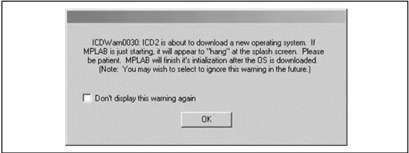
Also, since different MPLAB ICD 2 firmware is used for different families of devices, this dialog may appear when switching to a different device.
The firmware can be manually changed by following the steps in Section 4.2 “Upgrading the MPLAB ICD 2 Firmware (Operating System)”.
3.3 RUNNING THE PROJECT WIZARD
The MPASM assembler will be used in this project.
- To set up the first project, select Project>Project Wizard.
- Proceed to the second dialog of the wizard. The PIC18F452 should be selected.
- Proceed to the next dialog of the wizard to set up MPASM assembler as the language tool. In the “Active Toolsuite” pull-down, select “Microchip MPASM Toolsuite.” Make sure that the tools are set to the proper executables, by default located in the directory C:\Program Files\Micro-chip\MPASM Suite. MPASM assembler should be point-ing to mpasmwin.exe, MPLINK linker should be pointing to mplink.exe, and MPLIB librarian should be pointing to mplib.exe.
MPLAB ICD 2 Tutorial
FIGURE 3-3: WIZARD TOOLSUITE DIALOG
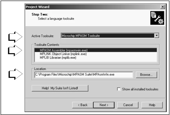
- Proceed to the next dialog of the wizard to give a name and location to
FIGURE 3-4: WIZARD ADD FILES
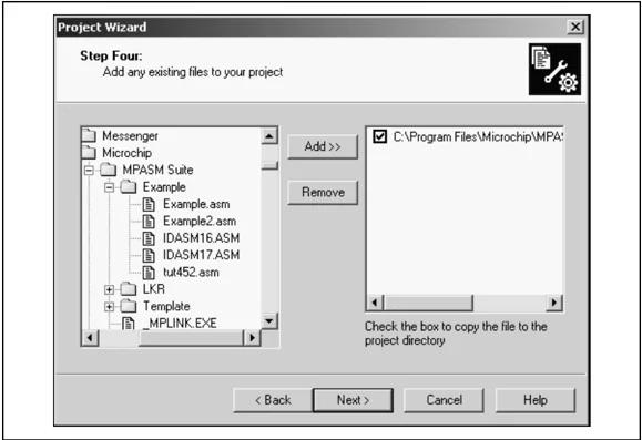
- The second file needed for this project is the linker script. Click on the C:\Program Files\Microchip\MPASM Suite\LKR folder to expand it, and then scroll down to select the file 18F452i.lkr. Make sure that the file name has an “i.”
Press ADD>> to move the linker script to the list on the right. You will not be copying this file into the project directory.
DS51331C-page 46 © 2007 Microchip Technology
MPLAB ICD 2 Tutorial
FIGURE 3-5: WIZARD ADD FILES – LINKER SCRIPT
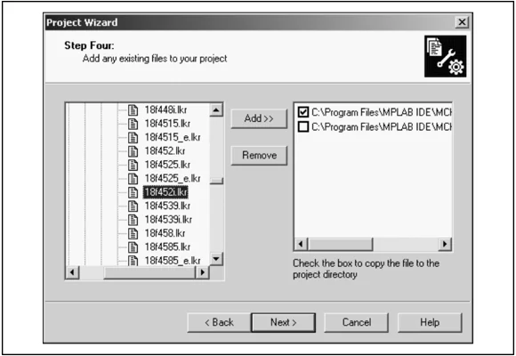
- Proceed to the Summary screen. If you have made any errors, click <Back to return to a previous wizard dialog. If everything is correct, click Finish.
3.4 VIEWING THE PROJECT
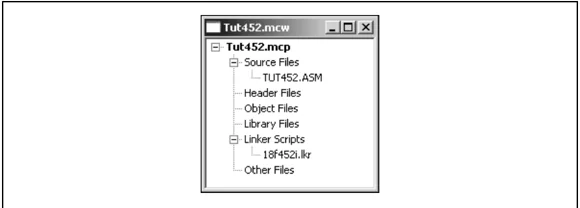
After exiting the wizard, the MPLAB IDE desktop will again be visible. Close all other windows on the desktop to see the Project window.
FIGURE 3-6: PROJECT WINDOW
Additional files can be added to the project using the project window. Right click on any line in the project window tree to pop up a menu with additional options for adding and removing files.
3.5 CREATING A HEX FILE
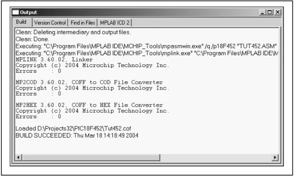
To create a hex file for debugging, select Project>Build All or right click on the project name in the project window and select “Build All” from the popup menu. MPASM assembler always makes a .hex file with the same name as the source .asm file.
FIGURE 3-7: OUTPUT WINDOW
DS51331C-page 48 © 2007 Microchip Technology
MPLAB ICD 2 Tutorial
3.6 SETTING DEBUG OPTIONS
Before you begin debugging your code, you will need to set up or check the default settings of several items.
3.6.1 Configuration Bits
To set Configuration bits to be programmed into the device, select Configure>Configuration Bits. By clicking on the text in the "Settings" column, these can be changed. In this dialog, the following Configuration bits should be set for this tutorial:
• Oscillator – EC-OS2 as RA6 (this is for PICDEM 2 Plus, if using another target, change to match)
• OSC Switch Enable – Disabled
• Power-Up Timer – Enabled
• Brown-Out Detect – Disabled
• Watchdog Timer – Disabled
• CCP2 MUX – RC1
• Stack Overflow Reset – Disabled
• Low Voltage Programming – Disabled
• All other Configuration bits should be disabled.
3.6.2 Programming Options
To set program options for this tutorial, select Debugger>Settings and click on the Program tab.
FIGURE 3-8: MPLAB® ICD 2 SETTINGS DIALOG, PROGRAM TAB
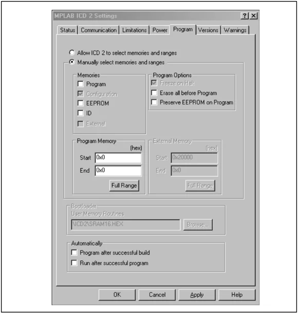
- The “Memories” section should have “Program” checked, and “EEPROM” and “ID” unchecked. When using MPLAB ICD 2 as a debugger, Configuration bits will always be programmed and the “Configuration” box will be checked and grayed out.
- For the PIC18FXX2 devices, all memory will be erased each time the chip is programmed. Therefore, in the “Program Options” section, “Erase all before Program” will have no effect.
MPLAB ICD 2 Tutorial
- The “Program Memory” addresses (“Start” and “End” address) set the range of program memory that will be read, programmed or verified. Click Full Range to set the address range to the maximum program memory available based on the device selected. The end of program memory is adjusted to leave room for the MPLAB ICD 2 debug executive. Programs cannot extend beyond this upper limit while using MPLAB ICD 2 as a debugger.
For additional information on all the options on the Program tab, see Section 5.4.5 “Program Tab”.
3.7 SETTING UP THE DEMO BOARD
Before beginning to debug, make sure the PICDEM 2 Plus Demo Board is set up as follows:
- EC OSC option has been selected by removing jumper J7
- LEDs have been enabled using jumper J6
- Power is supplied
3.8 LOADING PROGRAM CODE FOR DEBUGGING
Select Debugger>Program to program TUT452.hex into the PIC18F452 in the PICDEM 2 Plus demo board.
Note: The debug executive code is automatically programmed in upper program memory for MPLAB ICD 2 debug functions. Debug code must be programmed into the target PIC MCU to use the in-circuit debugging capabilities of the MPLAB ICD 2.
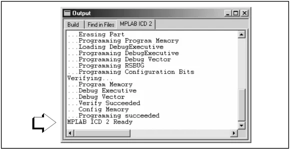
Programming may take a couple of minutes. During programming, the MPLAB ICD 2 tab of the Output dialog shows the current phase of operation. When programming is complete, the dialog should look similar to Figure 3-9.
FIGURE 3-9: OUTPUT WINDOW – MPLAB® ICD 2 TAB
3.9 RUNNING TUT452
MPLAB ICD 2 executes in Real-Time or in Step mode.
- Real time execution occurs when the PIC18F452 in the PICDEM 2 Plus demo board is put in the MPLAB IDE’s Run mode.
- Step mode execution can be accessed after the processor is halted.
These toolbar buttons can be used for quick access to commonly used debug operations.
| Debugger Menu | Toolbar Buttons |
|---|---|
| Run | □ |
| Halt | □□ |
| Animate | □□ |
| Step Into | □□ |
| Step Over | □□ |
| Step Out | □□ |
| Reset | □□ |
MPLAB ICD 2 Tutorial
Begin in Real-Time mode:
- Open the TUT452.asm file (double click on the file name in the Project Window or use File>Open).
- Select Debugger>Run (or click the Run toolbar button).
- On the demo board, turn the arrow on the potentiometer (RA0). Observe the LEDs. If the program were working correctly, the user would see a binary representation of the voltage value across the potentiometer. However, there is a bug in the TUT452 program. Section 3.10 “Debugging TUT452” will detail debugging the code and correcting it.
- Select Debugger>Halt (or click the Halt toolbar button) to stop the program execution.
- Select Debugger>Reset to reset the program.
3.10 DEBUGGING TUT452
Any of the following can prevent the TUT452 program from working.
- The A/D converter value is not being properly written to PORTB (LEDs).
- The A/D converter is not on or has not been set to convert.
- A typing error in the source code is causing the program to function improperly.
To explore the first possibility, set a breakpoint at the line of the file that writes the value of A/D result to PORTB.
-
Highlight or place the cursor on the following line of code from TUT452.asm:
movwf PORTB ;Write A/D result to PORTB
-
Right click to display a shortcut menu.
-
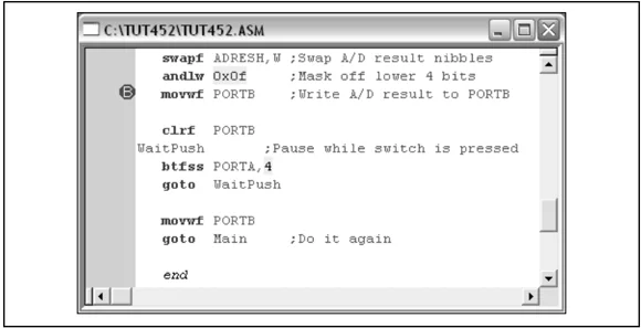
Select Set Breakpoint from the shortcut menu. This line is now marked as a breakpoint (B in red stop sign) as shown in Figure 3-10.
MPLAB® ICD 2 User’s Guide
FIGURE 3-10: SET BREAKPOINT
-
Select Debugger>Run (or click the Run toolbar button) to run the program once again in Real-Time mode. A breakpoint stops a program’s execution when the program executes the line marked as a breakpoint. However, the sample program is not halting.
-
Select Debugger>Halt (or click the Halt button on the toolbar) to halt the program now. In the source code window, the sample program will have halted on one of the two lines in the Wait routine as shown in Figure 3-11 (at the arrow).
MPLAB ICD 2 Tutorial
FIGURE 3-11: PROGRAM HALTED
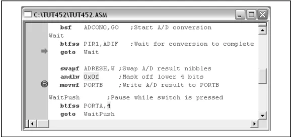
Based on the halt location and the fact that the program never reaches the breakpoint, it can be concluded that the problem is in the A/D conversion. The A/D flag for conversion complete is not being set. A/D conversion initialization and setup occurs at the beginning of the program.
-
To reset the program, select Debugger>Reset. The first instruction should be indicated with a green arrow.
-
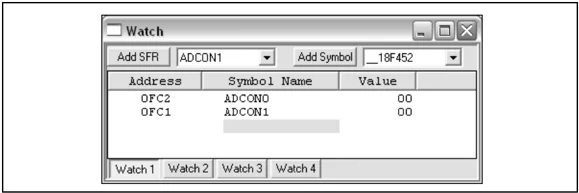
Open a new Watch window to watch the A/D register value change as the program executes. Select View>Watch. The Watch dialog opens with the Watch_1 tab selected. Select “ADCON0” from the list next to Add SFR, and then click the button. ADCON0 is added to the Watch window. Repeat for ADCON1. The selected symbols should now be visible in the Watch window as shown in Figure 3-12.
FIGURE 3-12: WATCH WINDOW
-
In the TUT452.asm source code, set a breakpoint at the first instruction after Start. Highlight or place the cursor in the following line of code from TUT452.asm: clr f PORTB ;Clear PORTB Right click to display a shortcut menu. Select Set Breakpoint from the shortcut menu. This line will now be marked as a breakpoint.
-
Select Debugger>Run (or click the Run toolbar button) to run the program in Real-Time mode. This time the program will stop after it executes the breakpoint line of code and the instruction after the breakpoint will be indicated as shown in Figure 3-13.
MPLAB ICD 2 Tutorial
FIGURE 3-13: PROGRAM HALTED AFTER BREAK
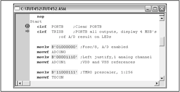
- Single step five times, select Debugger>Step (or click the Step toolbar button) to single step through the program. The following line of code should be indicated when finished:
movlw B'11000111' ;TMR0 prescaler, 1:256 - Examine the values of the registers ADCON0 and ADCON1 in the Watch window. Notice that ADCON0 has a value of 40 HEX. This corresponds to the binary value designated in the program, but is this value correct?
A review of the PIC18F452 Data Sheet (DS39564) section on A/D, indicates that the last bit should be a one, not a zero, to turn the A/D module on.
To fix this bug, change:
movlw B'01000000';Fosc/8, A/D enabledto:movlw B'01000001';Fosc/8, A/D enabled - Select File>Save to save the changes.
- Select Project>Build All to rebuild the project. A message will indicate that the program has been rebuilt. The MPLAB ICD 2 must be reprogrammed for the changes to take effect.
- Select Debugger>Program to reprogram the MPLAB ICD 2 with the changes. When the MPLAB ICD 2 dialog indicates ‘...Programming succeeded’, the program is ready to run again.
- Right click on the line of code that previously had the breakpoint (now indicated by a red stop sign outline). Select Remove Breakpoint.
- Select Debugger>Run (or click the Run toolbar button) to run the program in Real-Time mode. Turn the potentiometer (RA0) to change the value displayed on the LEDs.
The source code in this tutorial contained only one bug. However, real code may have more. Using the MPLAB ICD 2 and MPLAB IDE debugging functions, users can successfully find and fix the problems in their code.
3.11 PROGRAMMING THE APPLICATION
When the program is successfully debugged and running, usually the next step is to program the PIC MCU for stand alone operation in the finished design. When doing this, the resources reserved by the ICD are released for use by the application.
To program the application follow these steps:
- Disable MPLAB ICD 2 as a debug tool by selecting Debugger>Select Tool>None.
- Select MPLAB ICD 2 as the programmer in Programmer>Select Tool menu.
- Optional: Set up the ID in Configure>ID Memory (see Figure 3-14).
MPLAB ICD 2 Tutorial
FIGURE 3-14: USER ID MEMORY DIALOG
- Set up the parameters for programming on the Programmer>Settings Program tab.
- Select Programmer>Program.
Now MPLAB ICD 2 can reset and run the target (MPLAB ICD 2 can also be disconnected from the target; after selecting the Reset button, the application will run).
3.12 TUT452 MAIN ROUTINE AND SOURCE CODE
The main routine of TUT452.asm (Figure 3-14) begins by configuring PORTB, the A/D module and Timer0. It then waits for a Timer0 overflow to start the A/D conversion of the value from the potentiometer. When the conversion is complete, the value is displayed on the LEDs, and the program loops back to wait for another Timer0 overflow to start another A/D conversion.
For more information on A/D module operation and a list of related application notes, refer to the “PIC® 18C MCU Family Reference Manual” (DS39500).
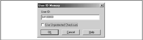
FIGURE 3-15: TUT452 MAIN ROUTINE FLOW
 START
Configure PORTB
as All Outputs
Configure A/D left justify, Fosc/8 clock 1 analog channel
Configure Timer0 Prescaler assigned to Timer0 1:256 prescale
Timer0 Overflow? No Yes
Start A/D Conversion
Conversion Complete? No Yes
Write A/D Result to PORTB
MPLAB ICD 2 Tutorial
;**************************************************** ;* TUT452.ASM * ;****************************************************
list p=18f452 include "p18f452.inc"
Reset_Vector ;Put a GOTO at code 0x0 ;reset address goto Start
Start code 0x0002A ;Start app beyond ;vector area clrf PORTB ;Clear PORTB clrf TRISB ;PORTB all outputs, ;display 4 MSB's of A/D ;result on LEDs movlw B'01000000' ;Fosc/8, ;A/D enabled movwf ADCON0 movlw B'00001110' ;Left justify, ;1 analog channel movwf ADCON1 ;VDD and VSS ref's movlw B'11000111' ;TMR0 prescaler,1:256 movwf T0CON
Main btfss INTCON,TMR0IF ;Wait for Timer0 ;to timeout goto Main bcf INTCON,TMR0IF
bsf ADCON0,GO ;Start A/D ;conversion Wait btfss PIR1,ADIF ;Wait for conversion goto Wait ;to complete
                swapf     ADRESH,W      ;Swap A/D result nib-
                                        bles
                andlw     0x0F          ;Mask off lower 4 bits
                movwf     PORTB         ;Write A/D result
                                        ;to PORTB
                clrf      PORTB
WaitPush btfss PORTA,4 ;Pause while switch goto WaitPush ;is pressed
                movwf     PORTB
                goto      Main          ;Do it again

                end
MPLAB® ICD 2
USER’S GUIDE
Chapter 4. Additional Topics
4.1 INTRODUCTION
As you work with MPLAB ICD 2 to develop your application, these are some additional topics that you may find useful.
Topics covered in this chapter are:
- Upgrading the MPLAB ICD 2 Firmware (Operating System)
- Creating/Loading a Hex File
- Special Linker Script Files
- ROMless Device Considerations
- ICD/ICE Devices
4.2 UPGRADING THE MPLAB ICD 2 FIRMWARE (OPERATING SYSTEM)
By default, MPLAB IDE will automatically download the correct and most up-to-date operating system for your selected device to the MPLAB ICD 2. This feature is selected from the Settings dialog, Status tab, by checking the checkbox “Automatically download firmware if needed”. If you have unchecked this checkbox, you may manually download the operating system (not recommended) as follows:
- Select Debugger>Download ICD2 Operating System or Programmer>Download ICD2 Operating System. The Select ICD Firmware File dialog will open.
- Select the firmware file to download from the list or browse for it. The file will be of the form
icdxxxxxx.hex, wherexxxxxxis the version number. See the readme file for information on which file supports which devices.
MPLAB® ICD 2 User’s Guide
- Click Open. MPLAB IDE will download the new operating system to the MPLAB ICD 2.
Note: If the wrong firmware is selected, MPLAB ICD 2 will experience unknown errors.
4.3 CREATING/LOADING A HEX FILE
Once the hex file is created/imported, you can use MPLAB ICD 2 to debug and/or program your code.
4.3.1 Creating a Hex File
If you need to create your hex code, MPLAB IDE offers a complete development environment.
To create a hex file in MPLAB IDE:
• Set up a project and related workspace to develop your application. For information on using projects and workspaces, please see MPLAB IDE Help.
• Use MPLAB Editor to create or import source code.
• Use language tools specified under the Project menu to assemble/compile your source code into hex code.
4.3.2 Loading a Hex File
If you already have a hex code file that you would like to program into your device, (i.e., you have used a tool other than the MPLAB IDE to generate your hex code), you may load the hex code to MPLAB IDE.
To load a hex file into MPLAB IDE:
• Use the File>Import command.
Additional Topics
4.3.3 Hex File Requirements
Whatever tool you use to develop your hex code, please keep in mind the following:
- Your code should be limited depending on the device because a portion of program memory on the device is reserved.
- The start of EEPROM data memory needs to be specified. For most PIC MCU's, the start should be at 0x2100 (org H'2100'). For PIC18FXXXX devices, the start should be at 0xF00000 (org H'F00000'). Please check the programming specification for your selected device to determine the correct address.
4.4 SPECIAL LINKER SCRIPT FILES
MPLAB IDE provides separate linker script files that reserve the resources used by the MPLAB ICD 2. There is a separate linker file for each supported device. The filenames contain the name of the device, followed by an “i”.
Examples:
- 18F452i.lkr – for the PIC18F452 device
- 18F4580i_e.lkr – for the PIC18F4580 device with extended memory
Customers that are using the MPLAB ICD 2 should use the linker file supplied for the device they are programming, instead of the standard linker files.
4.5 ROMLESS DEVICE CONSIDERATIONS
Working with ROMless (no on-chip program memory) devices is different from working with regular devices. You must create the routines that read/write memory. For more information, see:
- Implementing the External Memory Interface on PIC18C601/801 Application Note (AN778)
ICD2PDF.book Page 66 Friday, November 9, 2007 3:21 PM
4.5.1 PICDEM 18R
There is a Microchip demonstration board, PICDEM 18R, available for development using ROMless devices. Even if you do not purchase the demo board kit (DM163006), you can download the software and documentation for free from the Microchip website and use it to help you develop your own code:
- PICDEM 18R Demonstration Board User’s Guide (DS39565)
- PICDEM 18R Schematics
- PICDEM 18R Software
MPLAB IDE contains files that may be used with MPLAB ICD 2 and PICDEM 18R in the \ICD2 subdirectory when mapping External Memory for ROMless devices.
4.5.2 Additional Reference Documents
- PIC18C601/801 Data Sheet (DS39541)
- PIC18CXXX OTP In-Circuit Serial Programming (DS39028)
- PIC18XXXX MCU Family Product Overview (DS30327)