Additional Topics
4.5.3 External Memory
This section only applies to ROMless (PIC18C601/801) devices.
| File | Click the Browse button to select the location of the WriteProgramWord and EraseProgramMemory files. See PICDEM 18R Files. You must use a different memory routine file for the 8-bit bus width and the 16-bit bus width devices. The memory routine files must match the following naming conventions: <Memory Type><Bus Width>.<extension> where <Memory Type><Bus Width> does not exceed 8 characters. Valid 16-bit filename examples: 29F16016.hex SRAM16.hex Valid 8-bit filename examples: 29F16008.hex SRAM08.hex See the \ICD801\Source folder for information on writing your custom routines. These code routines will be used to program memory. They must be relocatable and comply with the format used in the included source files. |
|---|---|
| Use Default Program Routines | Select this option to use the default memory routines provided with MPLAB IDE instead of providing your own memory routines. See PICDEM 18R Files. |
4.5.4 PICDEM 18R Files
There is a folder called \ICD2 that was copied into the MPLAB IDE installation directory. This folder has two files which can be used with the PICDEM 18R demo board (DM163006):
- SRAM16.HEX – allows program download to the static RAM
- 29F16016.HEX – allows program download to the Flash memory
When using PICDEM 18R, you must use one of the above files in the “Location of WriteProgramWord and EraseProgramMemory” dialog on the MPLAB ICD 2 Advanced Dialog. Also, you must remember to do an erase before programming as this is not done automatically.
For your own design, which probably has different programming algorithms for the memory on your target, you must substitute your own memory read/write routine in order for the MPLAB ICD 2 to download code. See the PICDEM 18R documentation for information on writing your custom routines. These code routines will be used to program your memory and care must be taken to ensure they are relocatable and comply with the format used in the included source files.
4.6 ICD/ICE DEVICES
Special ICD versions of some devices (Device-ICD) are available to provide the clock, data and MCLR functions required for in-circuit debugging on dedicated pins. Therefore, the ICD version necessarily has a larger pin count than the original device. However, no pins are lost to in-circuit debug operation.
Also, some devices have ICE versions (Device-ICE) for use with an emulator. However, these device may be used with MPLAB ICD 2 to provide the functionality of an ICD device.
Currently, the following debug configurations are available:
• Device has no built-in debug circuitry. Therefore, Device-ICD must be used for development.
• Device has built-in debug circuitry for development. No Device-ICD/ICE available.
• Device has built-in debug circuitry for development. Device-ICD/ICE available, with built-in debug circuitry plus additional pins/memory for development.
ICD2PDF.book Page 69 Friday, November 9, 2007 3:21 PM
MPLAB® ICD 2
USER’S GUIDE
Chapter 5. ICD Function Summary
5.1 INTRODUCTION
When you select MPLAB ICD 2 from the Debugger menu, debugging functions will be added to MPLAB IDE.
When you select MPLAB ICD 2 from the Programmer menu, programming functions will be added to MPLAB IDE.
The functions made available are summarized here.
MPLAB ICD 2 functions are added to MPLAB IDE as follows:
- Debugging Functions
- Programming Functions
- Settings Dialog
- Setup Wizard
- Advanced Breakpoints Dialog
5.2 DEBUGGING FUNCTIONS
When you select MPLAB ICD 2 from the Debugger menu, debug items will be added to the following MPLAB IDE functions:
- Debugger Menu
- Toolbars
- Right Mouse Button Menus
5.2.1 Debugger Menu
Run F9
Execute program code until a breakpoint is encountered or until Halt is selected.
Execution starts at the current program counter (as displayed in the status bar). The current program counter location is also represented as a pointer in the Program Memory window. While the program is running, several other functions are disabled.
Animate
Animate causes the debugger to actually execute single steps while running, updating the values of the registers as it runs.
Animate runs slower than the Run function, but allows you to view changing register values in the Special Function Register window or in the Watch window.
To Halt Animate, use the menu option Debugger>Halt instead of the toolbar Halt or F5.
Halt F5
Halt (stop) the execution of program code. When you click Halt, status information is updated.
Step Into F7
Single step through program code.
For assembly code, this command executes one instruction (single or multiple cycle instructions) and then halts. After execution of one instruction, all the windows are updated.
For C code, this command executes one line of C code, which may mean the execution of one or more assembly instruction, and then halts. After execution, all the windows are updated.
Note: Do not step into a SLEEP instruction.
DS51331C-page 70 © 2007 Microchip Technology
ICD Function Summary
Step Over F8 Not available on MPLAB ICD 2. Performs the same as Step Into.
Step Out Not available on MPLAB ICD 2.
Reset F6 Issue a Reset sequence to the target processor. This issues a MCLR to reset the Program Counter to the Reset vector. If the processor is running it will continue running from the Reset vector address.
Breakpoints F2 Open the Breakpoint dialog. Set multiple breakpoints in this dialog; however, only one breakpoint is enabled at a time.
Note: You may also right click on a line of code to set a breakpoint.
Advanced Breakpoints Open the Advanced Breakpoint dialog. Setup advanced breakpoint features for devices that support this ICD feature.
MPLAB ICD 2 Setup Wizard Launch the wizard to help you set up the MPLAB ICD 2.
Program Download the debug executive module (if selected in Program tab) and your code to the target device.
Read Read target memory. Information uploaded to MPLAB IDE.
Read EEPROM Read device EEPROM data and then reset.
MPLAB® ICD 2 User’s Guide
Abort Operation Abort any programming operation (e.g., program, read, etc.) Terminating an operation will leave the device in an unknown state.
Connect Establish communications between the MPLAB ICD 2 and PC.
Download ICD2 Operating System Download MPLAB ICD 2 operating system.
Settings Opens the MPLAB ICD 2 Settings dialog. Set up communication, output file, power and program options. Also, find out information about the current system configuration and device limitations.
5.2.2 Toolbars
When the MPLAB ICD 2 is selected as a debugger, these toolbars are displayed in MPLAB IDE:
- Standard debug toolbar (Run, Halt, Step Into, Step Over, Reset). See MPLAB IDE Help for more information.
- MPLAB ICD 2 debug toolbar (Program Target Device, Read Target Device, Read device EEPROM, Reset and Connect to ICD).
5.2.3 Right Mouse Button Menus
The following will appear on the right mouse menus in code displays, such as program memory and source code files:
Set/Remove Breakpoint Set or remove a breakpoint at the currently selected line.
Enable/Disable Breakpoint Enable or disable a breakpoint at the currently selected line.
ICD Function Summary
Breakpoints Remove, enable or disable all breakpoints.
Run To Cursor Run the program to the current cursor location. Formerly Run to Here.
Set PC at Cursor Set the Program Counter (PC) to the cursor location.
5.3 PROGRAMMING FUNCTIONS
When you select MPLAB ICD 2 from the Programmer menu, program items will be added to the following MPLAB IDE functions:
- Programmer Menu
- Toolbar
5.3.1 Programmer Menu
MPLAB ICD 2 Setup Wizard Launch the ICD setup wizard.
Program Program specified memory areas: program memory, Configuration bits, ID locations and/or EEPROM data.
Read Read specified memory areas: program memory, Configuration bits, ID locations and/or EEPROM data.
Verify Verify programming of specified memory areas: program memory, Configuration bits, ID locations and/or EEPROM data.
Erase Part Erase all data on the PIC MCU device including memory, ID and Configuration bits.
ICD2PDF.book Page 74 Friday, November 9, 2007 3:21 PM
Blank Check Check to see that all device memory is erased/blank.
Release from Reset Set \overlineMCLR to VDD.
Hold in Reset: Set \overlineMCLR to ground (zero.)
Abort Operation Abort any programming operation (e.g., program, read, etc.) Terminating an operation will leave the device in an unknown state.
Connect Establish communications between the MPLAB ICD 2 and PC.
Download ICD2 Operating System Download MPLAB ICD 2 operating system.
Settings Opens the MPLAB ICD 2 Programmer dialog. Set up communication, output file, power and program options. Also, find out information about the current system configuration and device limitations.
5.3.2 Toolbar
Program target device Program specified memory areas: program memory, Configuration bits, ID locations and/or EEPROM data.
Read target device Read specified memory areas: program memory, Configuration bits, ID locations and/or EEPROM data.
ICD Function Summary
Verify target device memory Verify programming of specified memory areas: program memory, Configuration bits, ID locations and/or EEPROM data.
Erase target device Erase all data on the PIC MCU device including memory, ID, and Configuration bits.
Verify target device is erased Check to see that all device memory is erased/blank.
Reset and Connect to ICD Establish communications between the MPLAB ICD 2 and PC.
5.4 SETTINGS DIALOG
Select either Debugger>Settings or Programmer>Settings to open the Settings dialog and set up the MPLAB ICD 2.
• Status Tab • Communication Tab • Limitations Tab • Power Tab • Program Tab • Versions Tab • Warnings Tab
5.4.1 Status Tab
This tab of the MPLAB ICD 2 Programmer dialog allows you to set connection and message options.
ICD Function Summary
5.4.2 Communication Tab
This tab of the MPLAB ICD 2 Programmer dialog allows you to set how the MPLAB ICD 2 and the PC communicate.
5.4.3 Limitations Tab
This tab of the MPLAB ICD 2 Programmer dialog allows you to view MPLAB ICD 2 limitations for your selected device. Brief limitations are shown in the text box under the device. For more detailed limitations, click Details.
5.4.4 Power Tab
This tab of the MPLAB ICD 2 Programmer dialog allows you to view MPLAB ICD 2 and target power parameters and set the MPLAB ICD 2 to power the target.
View values for Target VDD, Target VPP and MPLAB ICD 2 VPP. If you know the values have changed since you opened the dialog, you may click Update to see these values update immediately or wait for one of the conditions specified on the dialog.
Click in the checkbox to enable/disable “Power target circuit from MPLAB ICD 2 (5V VDD)”.
5.4.5 Program Tab
This tab of the MPLAB ICD 2 Programmer dialog allows you to set up debug/programming options.
• Allow ICD 2 to select memories and ranges – MPLAB ICD 2 uses your selected device and default settings to determine what to program.
• Manually select memories and ranges – you select the type and range of memory to program.
TABLE 5-1: MANUAL SELECTION OPTIONS \begin{tabular}{|l|p{0.7\textwidth}|} \hline \multicolumn{2}{|l|}{\textbf{Memories}} \ \hline Program & Check to program Program Memory into target. \ \hline Configuration & Check to program Configuration Bits into target. \textbf{Note:} This memory is always programmed when in Debug mode. \ \hline EEPROM & Check to erase and then program EEPROM memory on target. Uncheck to erase EEPROM memory on target. \ \hline ID & Check to program ID Memory into target. \ \hline External & Check to program External Memory into target. \textbf{Note:} To select External, your device must support external memory and you must have enabled “Use External Memory” in the External Memory Settings dialog (\textit{Configure>External Memory}). \ \hline \multicolumn{2}{|l|}{\textbf{Program Options}} \ \hline Freeze on Halt & Set/clear all peripherals to freeze on halt. \ \hline Erase all before Program & Check to erase all memory before programming begins. Unless programming new or already erased devices, it is important to have this box checked. If not checked, the device is not erased and program code will be merged with the code already in the device. \ \hline \end{tabular}
ICD Function Summary
TABLE 5-1: MANUAL SELECTION OPTIONS (CONT.)
TABLE 5-2: BOOTLOADER OPTIONS
Enter your own bootloader or Browse for the file in User Memory Routines.
TABLE 5-3: AUTOMATIC OPTIONS
| Program after successful build | If the project builds successfully (no errors), automatically program the device. |
|---|---|
| Run after successful program | If the device programs successfully (no errors), run the program. |
Note: If you are using the MPLAB ICD 2, you must check the “Automatically Program after successful build” in the MPLAB ICD 2 settings dialog on the Program tab. Do not check “Automatically Run after successful program.”
5.4.6 Versions Tab
This tab of the MPLAB ICD 2 Programmer dialog allows you to view the version numbers for MPLAB ICD 2 elements.
| MPLAB® ICD 2 Version | PC software DLL version |
|---|---|
| Firmware | MPLAB ICD 2 operating system |
| Firmware Type | Device type for firmware |
| Firmware Version | MPLAB ICD 2 operating system version |
| Bootloader Version | MPLAB ICD 2 bootloader version |
| Debug Exec Version | Debug executive module version |
5.4.7 Warnings Tab
This tab of the MPLAB ICD 2 Programmer dialog allows you to select which MPLAB ICD 2 warning messages you wish to display in the Output window. This is useful for disabling warnings that you know you will ignore and do not want to view.
ICD Function Summary
Click in the checkbox next to a warning in the list to enable/disable the warning. Checked is enabled; unchecked is disabled.
5.5 SETUP WIZARD
A setup wizard is available from Debugger>MPLAB ICD 2 Setup Wizard to help walk you through setting up your MPLAB ICD 2.
• Setup Wizard – Welcome • Setup Wizard – Select a Port • Setup Wizard – Select Target Power • Setup Wizard – Enable Auto Connect • Setup Wizard – Enable Automatic OS Download • Setup Wizard – External Memory • Setup Wizard – Summary
5.5.1 Setup Wizard – Welcome
When you first select MPLAB ICD 2 as a debugger or programmer, the MPLAB ICD 2 Setup Wizard will open.
Follow the dialogs in the MPLAB ICD 2 Wizard to set up MPLAB ICD 2 for use with MPLAB IDE.
Click Next to continue.
5.5.2 Setup Wizard – Select a Port
Step 1: Select a communications method – Select a communications port to which you will attach the MPLAB ICD 2.
• COM Port – Select either a serial port (COM1-COM4) or a USB port (USB).
• Baud Rate – For a serial port, select 19200 or 57600.
Note: You may wish to try the higher baud rate to see if you can communicate at this speed. If you experience errors, return to the lower baud rate.
Click Next to continue.
5.5.3 Setup Wizard – Select Target Power
Step 2: Select target power source – Choose from where the target board will get its power.
• Target has own power supply – The target board will use its own power supply.
• Power target from the MPLAB ICD 2 – You may use the MPLAB ICD 2 to power the target board as long as:
- MPLAB ICD 2 has a power supply (the USB cannot provide enough power for both the MPLAB ICD 2 and a target board.)
- Target board power requirements are within what the MPLAB ICD 2 provide.
Click Next to continue.
5.5.4 Setup Wizard – Enable Auto Connect
Step 3: Enable auto-connection – Set up MPLAB IDE to automatically connect to MPLAB ICD 2 on project start-up.
• MPLAB IDE automatically connects to MPLAB ICD 2 – Check to connect on project start-up. Uncheck to connect manually, i.e., using Debugger>Connect.
CAUTION
If there is a device other than the MPLAB ICD 2 on the port when you auto-connect, damage to that device may result.
Click Next to continue.
ICD Function Summary
5.5.5 Setup Wizard – Enable Automatic OS Download
Step 4: Enable autodownload of operating systems – Automatically download the correct OS for the selected device.
Note: There are different operating systems for different devices.
• Required operating system automatically downloaded to MPLAB ICD 2 – Check to automatically download the correct OS for your selected device. The OS will be downloaded when MPLAB IDE detects that the current MPLAB ICD 2 operating system is not correct for the selected device or there is a newer version of this operating system. Uncheck to be prompted to download the OS. If you choose not to download the OS, it may be downloaded manually later using Debugger>Download ICD Operating System.
Note: Downloading an incorrect operating system will cause unknown errors. It is recommended that you allow MPLAB IDE to automatically download the OS.
Click Next to continue.
5.5.6 Setup Wizard – External Memory
Note: This page will only appear if you have selected a ROMless device (PIC18C601/801.)
Step 5: Specify amount of external memory – Specify the amount of external memory you will use for your ROMless device. The Start Address is always zero (0). Enter an End Address value in decimal or hex (use 0x before number.)
Click Next to continue.
5.5.7 Setup Wizard – Summary
Check the summarized information. If anything is incorrect, use Back to return to the dialog you need and change the information. Click Finish when you are satisfied with the MPLAB ICD 2 setup.
5.6 ADVANCED BREAKPOINTS DIALOG
In addition to the basic breakpoints that you may set (right-mouse menu and standard Breakpoint dialog), MPLAB ICD 2 has an Advanced Breakpoints dialog (Debugger>Advanced Breakpoints.)
The options on the Advanced Breakpoint Dialog are dependent on your selected device.
• PIC18F Devices – Regular PIC18F MCU devices.
• Extended PIC18F Devices V1 – Version 1 extended PIC18F devices have an extended instruction set (available for MPLAB C18 C compiler use) that may be enabled through a Configuration bit (XINST).
• Extended PIC18F Devices V2 – Version 2 extended PIC18F devices have the version 1 extended instruction set, as well as additional Breakpoint capabilities.
• dsPIC30F Devices – dsPIC30F DSC devices.
• dsPIC33F/PIC24 Devices – dsPIC33F DSC and PIC24 MCU devices.
5.6.1 PIC18F Devices
The Advanced Breakpoints Dialog for PIC18F devices contains the following options.
Breakpoint is in Program Memory
Check this checkbox if the breakpoint will be located in program memory. Then, enter the “Program Memory Address” as the location of the breakpoint.
ICD Function Summary
Breakpoint is in File Registers
Check this checkbox if the breakpoint will be located in data memory (file registers). Then:
• Read Access/Write Access – Specify file register access.
• File Register Address – Enter location of breakpoint.
• File Register Value – If “File Register Must be Equal to Following Value”, check the checkbox and then enter “File Register Value”.
Additional Breakpoint Setup
In addition to breakpoint memory setup, you may select the following:
• Break on Stack Over/Underflow – Break on stack overflow or underflow.
• Pass Count – For the breakpoint set above, break for the entered pass count value (0-255).
5.6.2 Extended PIC18F Devices V1
The Advanced Breakpoints Dialog for Extended PIC18F devices (version 1) contains the following options.
Breakpoint Number
These devices support up to three breakpoints. Enter a number and then set up that breakpoint below. Change the number to set up another breakpoint.
Breakpoint is in Program Memory
Check this checkbox if the breakpoint will be located in program memory. Then, enter the “Program Memory Address” as the location of the breakpoint.
Breakpoint is in File Registers
Check this checkbox if the breakpoint will be located in data memory (file registers). Then:
• Read Access/Write Access – Specify file register access.
• File Register Address – Enter location of breakpoint.
• File Register Value – If “File Register Must be Equal to Following Value”, check the checkbox and then enter “File Register Value”.
Additional Breakpoint Setup
In addition to breakpoint memory setup, you may select the following:
• Break on Stack Over/Underflow – Break on stack overflow or underflow.
• Pass Count – For the breakpoint set above, break for the entered pass count value (0-255).
5.6.3 Extended PIC18F Devices V2
The Advanced Breakpoints Dialog for Extended PIC18F devices (version 2) contains the following options.
5.6.3.1 BREAKPOINT PARAMETERS
These options apply to the breakpoint specified in “Breakpoint #”.
Breakpoint Number
These devices support up to three breakpoints. Enter a number and then set up that breakpoint below. Change the number to set up another breakpoint.
Breakpoint is in Program Memory
Check this checkbox if the breakpoint will be located in program memory. Then, enter the “Program Memory Address” as the location of the breakpoint.
ICD Function Summary
Breakpoint is in File Registers
Check this checkbox if the breakpoint will be located in data memory (file registers). Then:
• Read Access/Write Access – Specify file register access.
• File Register Address – Enter location of breakpoint.
• File Register Value – If “File Register Must be Equal to Following Value”, check the checkbox and then enter “File Register Value”.
Data Sample
Check this checkbox if the breakpoint will signify the start of data sampling. Then:
• File Register Address – Enter location of breakpoint.
Data samples will appear in the Output window under the ICD2 Data Sample tab. To have this information scroll, select “Scroll Data Sample Output” under Section 5.6.3.2 “Emulator Features”.
Additional Breakpoint Setup
In addition to the above breakpoint setup, you may select the following at the bottom of the dialog:
• Pass Count – For the breakpoint set above, break for the entered pass count value (0-255).
5.6.3.2 EMULATOR FEATURES
The following features apply independent of the breakpoint setup above.
Event Breakpoints
For all breakpoints:
• Break on Stack Over/Underflow – Break on stack overflow or underflow. (Future feature)
• Break on Watchdog Timer – Break on a WDT time-out. (Future feature)
• Break on SLEEP – Break on a SLEEP instruction. The SLEEP instruction will NOT be executed. Running or stepping from this point will execute the instruction after SLEEP.
Enable Stopwatch
Check to coordinate breakpoints with Stopwatch operation.
• Halt on Start Condition (Breakpoint 2)
- If checked, halt program (breakpoint 2 enabled) and program/Stopwatch go on Run.
- If unchecked, program continues to run (breakpoint 2 disabled) and Stopwatch is started.
• Halt on Stop Condition (Breakpoint 3)
- If checked, halt program (breakpoint 3 enabled) and Stopwatch.
- If unchecked, program continues to run (breakpoint 3 disabled), but Stopwatch halted.
• Reset Stopwatch on Run – Any time you run the program, reset the stopwatch to zero.
Scroll Data Sample Output
Check to scroll data sample information in the Output window, if selected under Section 5.6.3.1 “Breakpoint Parameters”.
ICD Function Summary
5.6.4 dsPIC30F Devices
The Advanced Breakpoints Dialog for dsPIC30F DSC devices contains the following options.
Breakpoint Combinations
This section is grayed out unless there are two breakpoints. The options are:
- Both breakpoints must occur at the same time to cause a break.
- Breakpoint 0/1 does not break until after breakpoint 1/0 occurs – Click Swap BPs to change the order.
Breakpoints
TABLE 5-4: PROGRAM MEMORY
TABLE 5-5: DATA MEMORY – BYTE OR WORD
TABLE 5-6: DATA MEMORY
ICD Function Summary
5.6.5 dsPIC33F/PIC24 Devices
The Advanced Breakpoints Dialog for dsPIC33F DSC and PIC24 MCU devices contains the following options.
• Breakpoints Tab
• Breakpoint Combinations Tab
• Emulator Features Tab
5.6.5.1 BREAKPOINTS TAB
Breakpoints
TABLE 5-7: PROGRAM MEMORY
TABLE 5-8: DATA MEMORY – BYTE OR WORD
| Breakpoint Type | X Bus Write Specific ByteX Bus Read Specific ByteY Bus Read Specific WordX Bus Write Specific WordX Bus Read Specific Word |
|---|---|
| Data Memory Address | Enter the Data Memory Address of the breakpoint. |
| Data Value | Specify a value that the Byte or Word must be equal to before breaking. |
| Pass Count Type | Enter the pass count type, if desired.Pass counting disabled – default.Event must occur pass count times.Break occurs pass count instructions after event. |
| Pass Count | Enter a pass count value, a number between 0 and 255. |
TABLE 5-9: DATA MEMORY
| Breakpoint Type | Y Bus ReadX Bus WriteX Bus Read |
|---|---|
| Data Memory Address | Enter the Data Memory Address of the breakpoint. |
| Pass Count Type | Enter the pass count type, if desired.Pass counting disabled – default.Event must occur pass count times.Break occurs pass count instructions after event. |
| Pass Count | Enter a pass count value, a number between 0 and 255. |
| Enable Data Sample | Check to enable data sampling. View data in Output window, ICD2 Data Sample tab. |
ICD Function Summary
5.6.5.2 BREAKPOINT COMBINATIONS TAB
Breakpoint(s) must previously have been set up in Section 5.6.5.1 “Breakpoints Tab” for options to be available here.
ANDED Breakpoints
Check the checkbox next to each breakpoint to AND together.
Breakpoint Sequencing
Select a breakpoint sequence.
Swap Breakpoints
Choose one breakpoint to swap with another.
5.6.5.3 EMULATOR FEATURES TAB
The following features apply independent of the breakpoint setup above.
Event Breakpoints
For all breakpoints:
• Break on Watchdog Timer – Break on a WDT time-out.
• Break on SLEEP – Break on a SLEEP instruction. The SLEEP instruction will NOT be executed. Running or stepping from this point will execute the instruction after SLEEP.
Enable Stopwatch
Check to coordinate breakpoints with Stopwatch operation.
• Halt on Start Condition (Breakpoint 1)
- If checked, halt program (breakpoint 1 enabled) and program/Stopwatch go on Run.
- If unchecked, program continues to run (breakpoint 1 disabled) and Stopwatch is started.
• Halt on Stop Condition (Breakpoint 0)
ICD2PDF.book Page 94 Friday, November 9, 2007 3:21 PM
- If checked, halt program (breakpoint 0 enabled) and Stopwatch.
- If unchecked, program continues to run (breakpoint 0 disabled), but Stopwatch halted. • Reset Stopwatch on Run – Any time you run the program, reset the stopwatch to zero.
Data Sample Scroll Output
Check to scroll data sample information in the Output window, if selected under Section 5.6.5.1 “Breakpoints Tab”.
ICD2PDF.book Page 95 Friday, November 9, 2007 3:21 PM
MPLAB ICD 2
MICROCHIP USER’S GUIDE
Part 2 – Troubleshooting
- Chapter 6. Troubleshooting Tips ........ 97
- Chapter 7. Self-Test ........ 105
- Chapter 8. General Troubleshooting ........ 109

ICD2PDF.book Page 96 Friday, November 9, 2007 3:21 PM
NOTES:
ICD2PDF.book Page 97 Friday, November 9, 2007 3:21 PM
MPLAB® ICD 2
MICROCHIP USER’S GUIDE
Chapter 6. Troubleshooting Tips
6.1 INTRODUCTION
Since many things in MPLAB IDE, MPLAB ICD 2 and the PIC MCU target application circuit can affect the operation of MPLAB ICD 2, it is important to understand the operation of each link in the chain of ICD functionality.
Figure 6-1 is a diagram showing the various links. Each link must be functional for MPLAB ICD 2 to program and debug. This section discusses these links to help find and fix problems if they occur.
FIGURE 6-1: CHAIN OF MPLAB® ICD 2 FUNCTIONALITY
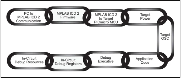
Functional links are covered as follows: • Link: PC to MPLAB ICD 2 Communications • Link: MPLAB ICD 2 Firmware • Link: MPLAB ICD 2 to Target PIC MCU Device • Link: Target Power • Link: Target Oscillator • Link: Application Code • Link: Debug Executive • Link: In-Circuit Debug Registers • Link: In-Circuit Debug Resources
6.2 LINK: PC TO MPLAB ICD 2 COMMUNICATIONS
This link is the foundation for all subsequent links. If it doesn't work, MPLAB IDE will issue communications errors. Make sure that the MPLAB USB drivers are installed according to the instructions. Look at the Windows hardware manager dialog under the USB section to see that the MPLAB ICD 2 driver is properly installed on the PC. If using RS-232, make sure that the FIFO buffers are turned off and flow control is set for hardware in the COMM driver dialog. If the MPLAB ICD 2 USB driver is not visible in the USB section of the Hardware Manager, go to the ICD2/Drivers subdirectory of the MPLAB IDE installation directory. Open the .htm files with a web browser to view details on driver installation for the appropriate operating system. See Section 2.3.1 “Setting Up Communications” for more information.
Troubleshooting Tips
6.3 LINK: MPLAB ICD 2 FIRMWARE
Be sure that the latest version of firmware is loaded in the MPLAB ICD 2. Updated firmware can be downloaded with the MPLAB IDE software. (See Section 4.2 “Upgrading the MPLAB ICD 2 Firmware (Operating System)” for automatically downloading firmware.) The latest production software should always be downloaded from the Microchip web site, www.microchip.com.
The version of firmware will determine which target PIC MCUs are supported. See the README file for the latest information on the firmware and on MPLAB ICD 2.
6.4 LINK: MPLAB ICD 2 TO TARGET PIC MCU DEVICE
Verify that all lines are connected and that no other signals or components are interfering with ICD signals on VPP, PGC and PGD. If MPLAB ICD 2’s VDD and VSS lines are not connected to the target power and ground, it will not work. MPLAB ICD 2 can provide VDD to the target (<200mA, 5 volts only) and to these output buffers when providing power to the target circuit (selected by the Debugger>Settings dialog Power tab, “Power target circuit from MPLAB ICD 2”). Otherwise, the target’s VDD will be used. VDD is sensed by MPLAB ICD 2 to check that voltage levels are correct. Powering from the target VDD allows level translation for target low-voltage operation. A simplified circuit for the internal buffer circuits of MPLAB ICD 2 is shown in Figure 6-2.
FIGURE 6-2: MPLAB® ICD 2 INTERNAL BUFFER CIRCUITS
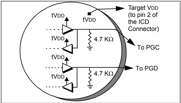
If MPLAB ICD 2 does not have voltage on its VDD line (pin 2 of the ICD connector) it will not operate. Using a scope, communications on PGC and PGD with a full target VDD to VSS peak-to-peak waveform should be seen. VPP should show +12, +5, and 0V levels depending upon the operation being performed. Signals should be seen on those lines only after performing an MPLAB ICD 2 function from the MPLAB user interface. Otherwise, all these lines should be idle and noise free.
6.5 LINK: TARGET POWER
MPLAB ICD 2 can work within a range of about 2V to 5.5V on the target PIC MCU's VDD. The application must be powered by its own power supply. Remember, that the PGC and PGD I/O drivers in MPLAB ICD 2 are powered from the target VDD (see Figure 6-2).
Troubleshooting Tips
6.6 LINK: TARGET OSCILLATOR
When programming a device, it will program without a running oscillator, but the debug function will not work unless the target oscillator is functioning. Unlike an in-circuit emulator, while debugging, MPLAB ICD 2 requires that the target PIC MCU is running.
Testing may be necessary to make sure that the target system is executing instructions properly. For instance, a small program could be written to flash an LED and then programmed into the target PIC MCU with MPLAB ICD 2 debug disabled. Disconnect the ICD and reset the target. If the LED does not flash, check the circuitry to find out why it's not operating. If MPLAB ICD 2 is connected after programming the target with debug disabled, MPLAB can still toggle the Reset. If it runs stand-alone but not with ICD connected (after selecting Debugger>Run in the MPLAB IDE), then the interconnections may be suspicious. Use a scope to look at PGC, PGD and VPP. Make sure that the oscillator starts up quickly. If it takes too long to get the target oscillator started, then MPLAB ICD 2 can time out and give errors.
Make sure that the correct Oscillator mode is selected (look at Configure>Configuration Bits). The Oscillator mode will depend upon the oscillator selected. Try HS mode for a crystal, and RC mode for an external resistor/capacitor oscillator. These settings may need to be changed for the final design, but they are some of the easiest modes to start with. Oscillator operation can be checked on OSC2 after Configuration bits are set at programming time and power is applied in debug or normal mode.
6.7 LINK: APPLICATION CODE
Verify that MPLAB ICD 2 is programming properly by either running an LED blink test similar to that described in Link: Target Oscillator or by programming code into the target device. MPLAB ICD 2 will execute a verify function after programming to confirm that the data in the target PIC MCU matches MPLAB ICD 2’s program memory. Programmer>Verify can also be selected manually to compare the target PIC MCU’s memory with the MPLAB IDE image. If the target PIC MCU has AVDD and AVSS, ensure that they are connected properly. These lines should be connected to power (VDD) and ground (VSS) respectively. Consult the device data sheet for details. MPLAB ICD 2 will not operate if any of these are available and not connected. Make sure that Low Voltage Programming is disabled (Configure>Configuration Bits).
6.8 LINK: DEBUG EXECUTIVE
When using the Debugger>Program function from MPLAB IDE, the debug executive will be downloaded and the in-circuit debug registers in the target PIC MCU will be enabled. Programming should always be done from the Debug menu, not the Programmer menu when debugging. When programming from the Programmer menu (after turning MPLAB ICD 2 off as a debugger), the debug executive will not be downloaded and the in-circuit debug registers will be disabled.
By looking at the Configure>Configuration Bits menu selection, it can be determined whether MPLAB is going to download the debug executive. If the bits labeled “Background Debug” are enabled, then the debug executive will be downloaded when the device is programmed.
6.9 LINK: IN-CIRCUIT DEBUG REGISTERS
Make sure that debug is enabled on the MPLAB ICD 2 dialog in MPLAB IDE before programming a device. By looking at the Configure> Configuration Bits dialog, it can be verified that the
Troubleshooting Tips
in-circuit debug registers are enabled. The line labeled “Background Debug” should say “Enabled.” Programming should be done from the Debug menu, not the Programmer Menu.
6.10 LINK: IN-CIRCUIT DEBUG RESOURCES
Look at the specific registers used for a device in the on-line help. The file registers or program memory areas reserved by MPLAB ICD 2 can not be used. If using the xxxxxi.lkr linker script (name ends in “i”), then, unless the script has been modified, these resources will be marked reserved and will not be available to the application. If the linker is not being used, use CBLOCK or EQUs for variable storage in the code, make sure that registers required by MPLAB ICD 2 are not used. The in-circuit debugger will not work if “code protect” or “table read protect” is enabled, if the Watchdog Timer is running or if the oscillator is not set to the correct mode by the Configuration bits. If using fast interrupts or the CALL FAST instruction, MPLAB ICD 2 uses the shadow stack and users will not be able to exit properly from the fast interrupt routine or CALL FAST function.
ICD2PDF.book Page 104 Friday, November 9, 2007 3:21 PM
NOTES:
DS51331C-page 104 © 2007 Microchip Technology