Chapter 7. Self-Test
7.1 INTRODUCTION
The Run Self Test button (Settings dialog, Status tab) is helpful in determining problems with the MPLAB ICD 2 module or target connection.
Self-Test features covered are:
- Target VDD
- Module VPP
- MCLR = GND
- MCLR = VDD
- MCLR = VPP
- Failed Self-Test Error – VPP/VDD High/Low
7.2 TARGET VDD
Tests the VDD provided from the MPLAB ICD 2 (5 volts only) if “Power target circuit from MPLAB ICD 2” is selected.
Pass/Fail codes:
0/0 = Pass VDD is within specified limits
01 = Min error VDD is below specified limits
80 = Max error VDD is above specified limits
An error can indicate:
- Target voltage/current mismatch from provided voltage/current
- MPLAB ICD 2 pod hardware problems
7.3 MODULE VPP
Tests the programming voltage (VPP) provided from the MPLAB ICD 2 to the target VPP/MCLR pin during a programming cycle
Pass/Fail codes: 00 = Pass VPP is within specified limits 01 = Min error VPP is below specified limits 80 = Max error VPP is above specified limits
An error can indicate: • The target VPP/MCLR pin is not correctly wired
7.4 MCLR = GND
Test the ability of the MPLAB ICD 2 to provide a ground level to the target VPP/MCLR pin for target reset
Pass/Fail codes: 00 = Pass Ground can be provided to target VPP/MCLR pin 80 = Max error Ground level too high for target VPP/MCLR pin
An error can indicate: • The target VPP/MCLR pin is not correctly wired
Self-Test
7.5 \overlineMCLR = V_DD
Test the ability of the MPLAB ICD 2 to provide V_DD to the target V_PP/\overlineMCLR pin during normal operation (such as Run).
Pass/Fail codes: 00 = Pass V_DD can be provided to target V_PP/\overlineMCLR pin 01 = Min error V_DD too low for target V_PP/\overlineMCLR pin 80 = Max error V_DD too high for target V_PP/\overlineMCLR pin
An error can indicate:
- Target voltage/current mismatch from provided voltage/current
- MPLAB ICD 2 pod hardware problems
7.6 \overlineMCLR = V_PP
Test the ability of the MPLAB ICD 2 to provide V_PP to the target V_PP/\overlineMCLR pin during programming operations.
Pass/Fail codes: 00 = Pass V_PP can be provided to target V_PP/\overlineMCLR pin 01 = Min error V_PP too low for target V_PP/\overlineMCLR pin 80 = Max error V_PP too high for target V_PP/\overlineMCLR pin
An error can indicate:
- The target V_PP/\overlineMCLR pin is not correctly wired
7.7 FAILED SELF-TEST ERROR – VPP/VDD HIGH/LOW
Symptom:
When connecting to the MPLAB ICD2 in MPLAB IDE or running a self-test (Debugger/Programmer>Settings>Status>Self Test), MPLAB IDE may report a self-test error in the Output window.
Cause:
This could be due to the firmware routines used to determine minimum and maximum voltages (a less than compare is used in one place while a less-than or equal-to is used in another).
Solution:
Check the actual voltages measured by the ICD. This can be found at Programmer/Debugger>Settings>Power. The Update button will cause these voltages to be remeasured and displayed. As long as the voltages displayed are within tolerance for the target device, the MPLAB ICD 2 unit can still be used for programming and debugging operations.
The firmware will be changed for better support of self-test functions.
DS51331C-page 108 © 2007 Microchip Technology
ICD2PDF.book Page 109 Friday, November 9, 2007 3:21 PM
MPLAB® ICD 2
MICROCHIP USER’S GUIDE
Chapter 8. General Troubleshooting
8.1 INTRODUCTION
Frequently Asked Questions (FAQs) and common problems are documented here to help you as you use the MPLAB ICD 2. Also, messages generated by the ICD and its tool limitations are referenced.
Topics covered in this chapter are:
- Frequently Asked Questions
- Common Communication Problems
- Common Problems
- Error and Warning Messages
- Limitations
8.2 FREQUENTLY ASKED QUESTIONS
Questions are listed in the order of most-to-least frequently asked.
8.2.1 Why does my system fail to program or verify?
Check the PGC, PGD and VPP connections and voltages as described in Chapter 2.‘Getting Started’. Make sure the target PIC MCU has power applied. If the target PIC MCU has AVSS and AVDD pins, verify that these are all connected properly.
8.2.2 Why do I need the ICD header adapters?
The low pin count parts that are supported by MPLAB ICD 2 could not be used very effectively if in-circuit debug pins are reserved – imagine losing three out of six I/O lines on an eight-pin part! For this reason, special bond-out PIC MCUs have been manufactured
that can emulate these low pin count parts with an adapter, and which will allow the use of all pins in the target application. The bond-out PIC MCU has the in-circuit communications pins to interface to MPLAB ICD 2.
The advantage of this is that the low pin parts can be used in development with MPLAB ICD 2. The disadvantage is that these parts cannot simply have an MPLAB ICD 2 connector on the target application for in-circuit debugging. These bond-out PIC MCUs are similar to emulator chips. They can support more than one device. Jumpers are available on the header boards to configure the chip to match the device under development. These low pin count devices can be programmed with MPLAB ICD 2 using the Universal Programmer Adapter or by putting an MPLAB ICD 2 connector on the target application to connect VPP, PGC and PGD on these parts.
8.2.3 I can't connect to MPLAB ICD 2. What do I do now?
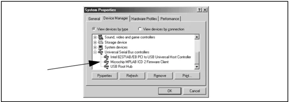
Is the MPLAB ICD 2 power light on? The LED should shine brightly. If it is dim, only USB may be connected and the user may need to connect the power supply. The RS-232 connection from the PC cannot supply power to MPLAB ICD 2, but a USB connection can. Note that some USB hubs cannot supply power. Check the on-line help for current troubleshooting hints. Are the USB drivers installed properly? The MPLAB ICD 2 USB driver should be visible in the Windows Device Manager dialog (see Figure 8-1). Some USB hubs cannot supply power to the attached USB devices. A power supply will need to be connected to MPLAB ICD 2 with these hubs.
DS51331C-page 110 © 2007 Microchip Technology
General Troubleshooting
FIGURE 8-1: SYSTEM PROPERTIES DIALOG
8.2.4 MPLAB ICD 2 responds with “Target not in debug mode error.” What does this mean?
Usually this means that MPLAB ICD 2 cannot communicate with the debug executive. The debug executive can only be downloaded by programming the target PIC MCU with the user’s application from the Debugger>Program menu selection. There are other reasons that the debug executive might not be able to communicate, such as target clock or power supply problems. Check the Configuration bits to see that the “Background Debug” is enabled. Look at Configure>Configuration Bits to make sure that the Watchdog Timer is disabled, code protection is turned off and that the oscillator setting is correct.
8.2.5 Can MPLAB ICD 2 operate with a target device running at low voltage?
Yes. As long as the target PIC MCU supports low-voltage operation, it can run down to about 2 volts VDD. There are level converters in the input/output buffers of the MPLAB ICD 2. These are powered from the VDD of the target device. Also, MPLAB ICD 2 will sense the operating voltage of the target and correctly adjust its functionality to deal with this operation, i.e., using the correct Flash erase algorithms. VDD needs to be selected “From Target” in the MPLAB ICD 2 “Settings” dialog, and have a power supply on the target for low-voltage operation.
8.2.6 Does MPLAB ICD 2 support Low Voltage Programming (LVP)?
No. But this does not mean that it will not work correctly when running at low-voltage VDD on the target. It just means that the programming voltages applied to VPP will always be +12V.
8.2.7 Why do I have problems when configuring the PLL Oscillator? MPLAB ICD 2 gets “hung up.”
This is a requirement of the actual PIC MCU. After programming the Configuration bits for the PLL Oscillator, power needs to be removed then reapplied to the target. If this is not done, the target PIC MCU will not have a clock. With no clock, Debug mode will not function. Also, if power is not removed and reconnected when switching to PLL mode, the device may run, but without the PLL multiplier.
8.2.8 When I try to install, why are the drivers not found, even though I can see them in the driver folders, and I point the driver wizard to the correct folder?
This problem can be solved by exiting from the driver install wizard, and going to the Control Panel “Add New Hardware” selection. After the system searches for new hardware, choose, “No, the device isn’t in the list.” Then choose “No, I want to select the hardware from a list.” Then choose “Universal Serial Bus Controller,” and when the Have Disk... button appears, go to the driver folder (MPLAB IDE\ICD2\Drivers) and select the proper driver.
8.2.9 Can I use code protection with MPLAB ICD 2?
No. Code protection, especially table read protection on any area in program memory will prevent MPLAB ICD 2 from functioning. Do not use any code protection or table read protection configura-
General Troubleshooting
tion settings when debugging with MPLAB ICD 2. Code protection can be enabled when programming a part for testing without MPLAB ICD 2.
8.2.10 How does MPLAB ICD 2 deal with Calibration Data?
It is automatically handled. Any values that are in program memory that are used by the PIC MCU for calibration data will be read and preserved by MPLAB ICD 2 when erasing, programming and debugging. No action is required to protect this data.
8.2.11 Why am I getting erratic values from my EEData area?
MPLAB ICD 2 can read the EEData areas directly, without going through the EECON register's required TABLRD sequence of instructions. The buffers that MPLAB uses can sometimes interfere with the user's code. Avoid going back and forth from program reads of data to MPLAB ICD 2 reads of the EEData area when single stepping code.
8.2.12 Why does my program keep resetting?
Check the Configuration bits settings (Configure>Configuration Bits) for your selected device. Some reset functions (such as Watchdog Timer Reset) are enabled by default.
8.2.13 Why is "Erase All Before Programming" grayed out?
In some of the newer Flash parts, the programming algorithm requires that non-contiguous areas of program memory are programmed in banks. For these parts, all memory must be erased before programming.
8.2.14 Can my program read and write from Port B or GPIO without interfering with MPLAB ICD 2?
Yes. When the in-circuit debug facilities are enabled, PGC and PGD are always used by MPLAB ICD 2, and user code that reads or writes from PORT B will not interfere. Note that the values read from PGC and PGD are not necessarily valid, and writes to these two pins will be ignored. In addition, if interrupts are enabled for changes on Port B, signals on PGC and PGD will not cause an interrupt.
8.2.15 Why are the timers behaving erratically when single-stepping?
This is one of the drawbacks of using the in-circuit debugger. Since code is actually running in the debug executive, timers can continue to run during the operation of the debug executive, even when the user’s application program is “halted.”
8.2.16 Why am I getting warnings and errors when using the PIC12F629/675 or PIC16F630/676?
The GP1/RA1 pins on these parts cannot be pulled high while using MPLAB ICD 2. Refer to the header board specification for more information on using MPLAB ICD 2 for these parts (DS51292).
8.2.17 What would make the power and busy LED blink on and off?
This may indicate that the target MPLAB ICD 2 connector is wired backwards (opposite from the wiring diagram). The blinking indicates that the MPLAB ICD 2 is shutting down due to high current. The following tests indicate that the target is connected backwards:
• Look for blinking Power and Busy LEDs (power may go out altogether).
• Execute a “Self-Test” and look for a min. error on
General Troubleshooting
“MCLR=VPP” (all other tests will probably pass).
- Use the default address range for the target controller and execute a “Program” cycle. A voltage level on pin 1 (VPP) of 7-8 volts is too low.
If the target was wired backwards, protection circuitry in the MPLAB ICD 2 will prevent damage to the module. Normal operation should be seen when the target is wired correctly.
The Error LED flashing indicates an over-voltage condition on either the clock or data line on the ICSP interface. This circuitry is in place to protect the buffers on the MPLAB ICD 2 from being damaged. When a high voltage is detected greater than 6.5V a clamping circuit brings the clock and data line low. Once this error occurs, MPLAB will need to be reinitialized and the fault removed for operation to resume normally.
8.2.18 What does the MPLAB ICD 2 “Self-Test” do?
The MPLAB ICD 2 Self-Test is helpful in determining problems with the MPLAB ICD 2 module or target connection. For more details, see Chapter 7.‘Self-Test”.
8.2.19 Why are the W, STATUS and BSR registers getting changed when using high priority interrupts with the RETFIE instruction?
The shadow registers, which are used for high priority interrupts and CALL FAST are used by MPLAB ICD 2. These are reserved resources for MPLAB ICD 2 operation. A problem will be encountered if a breakpoint is set inside a CALL FAST subroutine or inside the service routine for a high priority interrupt that uses the shadow registers with the RETURN FAST or RETFIE instruction.
8.2.20 When setting a breakpoint at the first location in my program, why does it stop at address 0001 rather than 0000?
MPLAB ICD 2 stops at the instruction after the breakpoint. This means that a breakpoint at address 0000 will be executed, then the program counter will be pointing at address 0001 when it gets a breakpoint. If a user needs to stop at the first instruction in their code, they must put a NOP at address 0000.
8.2.21 Why is my calibration memory displayed as the erase value?
MPLAB IDE is displaying the default memory value. A device read must be performed with MPLAB ICD 2 to display the actual value on the device.
8.2.22 When single stepping through the code, my timer times out, but why does my timer interrupt routine not execute?
When single stepping, the in-circuit debugger will not allow the PIC MCU to respond to interrupts. If it did, and users had external interrupts, then single stepping would almost always end up in interrupt routines. To debug an interrupt, set a breakpoint inside the Interrupt Service Routine and Run to get a breakpoint after the interrupt.
8.2.23 How do I program a ROMless (PIC18C601/801) device?
For these devices, you must create the routines that read/write memory. See Section 4.5 “ROMless Device Considerations” for details.
DS51331C-page 116 © 2007 Microchip Technology
General Troubleshooting
8.2.24 Why can't I step through a return for my dsPIC30F device?
Make sure that you have:
• checked the option to build for ICD, i.e., go to Project>Build Options>Project, MPLAB LINK30 tab, and check “Link for ICD2”.
• initialized the software stack, i.e., use the startup module libpic30.a (for MPLAB C30) or crt0.o (for MPLAB ASM30) or consult a template to write your own SP and SPLIM initialization code.
Then you should able to step through a return (from a function, etc.)
8.3 COMMON COMMUNICATION PROBLEMS
The following are a list of common problems with MPLAB ICD 2 communications, both USB and serial.
8.3.1 Communications cannot be established with MPLAB ICD 2
First, click Debugger>Connect. If you cannot establish communications with MPLAB ICD 2, follow the steps below. If communications still cannot be established, contact Microchip Engineering Support.
8.3.1.1 IN GENERAL
- Check that the RS-232 or USB cable is connected securely to the MPLAB ICD 2 and the host computer.
- Check that the modular cable is connected securely to the demo board/target application and the MPLAB ICD 2 module.
- Make sure there is power to the demo board/target application. Check VDD Source in the MPLAB ICD 2 Settings dialog, Power tab.
- Check that the device is plugged into the demo board/target application correctly; e.g., all pins are plugged into the socket and the device is correctly oriented.
8.3.1.2 SERIAL COMMUNICATIONS
- Make sure the power supply is connected and the Power LED on the MPLAB ICD 2 module is on.
- There may be a driver-hardware incompatibility; try changing Flow Control to Hardware and/or turning off the FIFO for the serial port.
For specific instructions, see Section 8.3.1.3 “Changing Serial Port Settings”.
- Check the settings on the MPLAB ICD 2 Setting dialog, Communication tab. Make sure you selected the correct COM port and baud rate for your application.
Note: If you are having problems at a COM port baud rate speed of 57600, switch back to the initial speed of 19200.
- Try connecting the MPLAB ICD 2 module to a different port. When first connecting to the MPLAB ICD 2, the default COM port is COM1. If you are using the MPLAB ICD 2 on another COM port, select Debugger>Settings and then click the Communications tab. Set your COM port and baud rate here.
- Make sure that a COM port is properly set up exclusively for use by the debugger. Check the resources to ensure they are operating properly and that there are no conflicts with other devices. This commonly happens when you have a modem or other serial device that is improperly configured. Consult your Windows manual or other reference literature. You can try removing, reconfiguring, or disabling the conflicting device, but only do so if you are familiar with those procedures.
General Troubleshooting
- If you have a COM port but MPLAB IDE will not let you select it (the option is grayed out) you may be able to assign the port manually by editing the mplab.ini file. Typically, this occurs if you have a gap in your COM port list (i.e., you have a COM1, COM2, and a COM4, but no COM3). In this case you may be able to fix it by opening mplab.ini (use Find to locate this file) and editing the section called [MPLAB ICD 2] so that the setting CommPort=1 is set to the port you want selected. This is just a work-around to a deeper problem in which Windows is incorrectly reporting port availability through the 16-bit driver.
8.3.1.3 CHANGING SERIAL PORT SETTINGS
Complete the following steps to change the Flow Control and FIFO settings for a serial communications port on a PC running the Windows operating system.
Windows 98/ME
- On your PC, select Start>Settings>Control Panel.
- In the Control Panel, double click the System Icon.
- In the Systems Properties dialog, click the Device Manager tab.
- If necessary, expand the Ports selection by clicking the “+” sign next to it.
- Double click the I/O port to which the MPLAB ICD 2 is connected.
- In the Flow Control field, select Hardware.
- Click the Advanced button, deselect the “Use FIFO” box, and click OK.
- Reboot the PC to implement the change.
Windows NT
Note: You may need administrator privileges on your computer to change these settings.
- On your PC, select Start>Settings>Control Panel.
- In the Control Panel, double click the Ports Icon.
- Double click the I/O port to which the MPLAB ICD 2 is connected.
- Select the Port Settings tab.
- In the Flow Control field, select Hardware.
- Click the Advanced button, deselect the “Use FIFO” box, and click OK.
- Reboot the PC to implement the change.
Windows 2000/XP
Note: You may need administrator privileges on your computer to change these settings.
- On your PC, select Start>Settings>Control Panel.
- In the Control Panel, double click the System Icon.
- In the Systems Properties dialog, click the Hardware tab and click the Device Manager button.
- Double click “Ports (COM & LPT)” to expand the Ports selection.
- Double click the I/O port to which the MPLAB ICD 2 is connected.
- Select the Port Settings tab.
- In the Flow Control field, select Hardware.
- Click the Advanced button, deselect the “Use FIFO” box, and click OK.
- Reboot the PC to implement the change.
General Troubleshooting
8.3.1.4 USB COMMUNICATIONS
CAUTION If the Windows OS picked a USB driver, MPLAB ICD 2 will not work. Follow the instructions in ICD2\Drivers\clnicd2.htm of the MPLAB IDE installation directory to remove the Windows drivers and replace them with the correct USB drivers.
- If MPLAB ICD 2 is powering a target application, make sure a power supply is connected and the Power LED on the MPLAB ICD 2 module is on.
- Make sure you have used the MPLAB IDE supplied USB driver for MPLAB ICD 2.
8.3.2 Connection failure occurs when using a COM port 2, 3 or 4
When first connecting to the MPLAB ICD 2, the default COM port is COM1. If you are using the MPLAB ICD 2 on another COM port, select Debugger>Settings and then click the Communications tab. Set your COM port and baud rate here.
8.3.3 MPLAB ICD 2 Connects But Target Operations Fail
This can indicate that the VDD setting is incorrect.
The MPLAB ICD 2 can provide VDD to the target (5 volts only). This is set in the MPLAB ICD 2 Debugger Settings dialog, Power tab. If “Power target circuit from MPLAB ICD 2” is selected, the MPLAB ICD 2 will provide VDD to the target (the target does not need to be powered). However, if the target needs a voltage other than 5V or more than 200mA of current, then the target cannot be powered by MPLAB ICD 2 and will require its own power source.
When you click the Reset button in Debug mode to reset the program, it will go to zero and halt. The Reset command will not rerun the program when the MPLAB ICD 2 is in Debug mode.
8.3.4 Command to program/erase target memory failed
Make sure that you have selected the appropriate Bus Width and Oscillator settings for the device you are programming.
8.3.5 Programming error occurs when programming a range of memory on PIC18C601/801
For the PIC18C601/801, you need to align the End Address + 1 so it can be divided by 8. For example, 0x7FF or 0x1FFF7. If you receive a programming error due to an incorrect End Address, you need to perform a reconnect, correct the End Address and select Program again.
8.4 COMMON PROBLEMS
The following are a list of common problems you may encounter.
8.4.1 Debug Mode Not Working
- Make sure you have selected all of the areas of the device that you want to program. Select Debugger>Settings and click on the Program tab. Select Memories as desired.
- If you are using the Start/End Address fields in the Memory Addresses section of the MPLAB ICD 2 Settings dialog (Debugger>Settings, Program tab), ensure that the Start Address is set to the beginning of an 8-byte block and the End Address is set to the end of an 8-byte block. For example, a Start Address of 0x10 and an End Address of 0x1F.
General Troubleshooting
8.4.2 Can't uncheck programming of Configuration bits in Debug mode
For MPLAB ICD 2 to function in Debug mode, the ICD must ensure that the Background Debug Configuration bit is programmed on the target. Therefore, configuration memory is always programmed when in Debug mode.
8.4.3 When single stepping, the program runs too slowly
Upload of Data Issue
Data is uploaded from the MPLAB ICD 2 depending on the amount of data displayed in the IDE, i.e., the size and amount of open debug windows.
• If your program is running slow, consider closing some windows or using Watch windows to view specific registers.
• If not all register data is being updated, you probably do not have all the registers visible when you run/step. That is, if you step, then scroll to find a register, it will not have the updated data from the step execution.
8.4.4 Single Stepping Slow when Programmer Enabled
If you have a programmer enabled when using MPLAB ICD 2 to debug a part with EEData, your stepping through code will be very slow. Disable the programmer to speed up stepping time.
The slowdown occurs because the programmer must attach to the entire range of EEData so it can be programmed. The debugger, seeing that something is attached to the EEData (whether a programmer or EEData Display) will read back the entire range after each step in case the data was modified while running.
8.4.5 When single stepping, the program runs too quickly OR some registers are not updated
This is an upload of data issue. See Section 8.4.3 “When single stepping, the program runs too slowly”.
8.4.6 When halting, single stepping, or stopping on a breakpoint, MPLAB IDE seems to lock up
Your program may not have locked up, but may be running very slowly. This is an upload of data issue. See Section 8.4.3 “When single stepping, the program runs too slowly”.
Also, if you are using PIC16F87X device, the first program memory location (address 0x0000) must be a NOP instruction or you will not be able to single step past location zero.
8.4.7 The following I/O pins are not functioning correctly: RB6 or RB7
These pins are reserved for debugging.
8.4.8 One or more of my memory addresses (Program or GPR) is not correct
Several GPR's and Program Memory locations are reserved for debugging.
8.4.9 EEPROM window does not reflect changes
In order to see the changes in the window, you must do a read of the memory.
8.4.10 Stack window does not reflect changes/is blank
This is a tool limitation. See Chapter 11.“Limitations”.
8.4.11 Program keeps resetting
See Section 8.2.12 “Why does my program keep resetting?”.
General Troubleshooting
8.4.12 Execute Reset or MCLR command, program does not rerun
When you select Debugger>Reset to reset the program, it will go to zero and halt. The Reset command will not rerun the program when the MPLAB ICD 2 is in Debug mode.
8.4.13 File Register window does not display Top-of-Stack Registers
The three Top-of-Stack registers (TOSU, TOSH, and TOSL) are not displayed in the File Registers window when using the MPLAB ICD 2.
8.4.14 Power and busy LED blink on and off
See Section 8.2.17 “What would make the power and busy LED blink on and off?”.
8.5 ERROR AND WARNING MESSAGES
MPLAB ICD 2 generates several error and warning messages. Details on the meanings of most messages may be found in on-line help for MPLAB ICD 2.
Warning messages may be selected to display or not display using the Warnings tab of the Settings dialog.
All messages may be output to a file for debugging by selecting the “Output to Debug File” checkbox on the Status tab of the Settings dialog.
8.6 LIMITATIONS
MPLAB ICD 2 has limitations for both its debugger and programmer modes. These, and additional device-specific limitations, may be found in on-line help for MPLAB ICD 2.
ICD2PDF.book Page 126 Friday, November 9, 2007 3:21 PM
NOTES:
MPLAB® ICD 2
USER’S GUIDE
Appendix A. Hardware Specifications
A.1 INTRODUCTION
Hardware specifications for MPLAB ICD 2 system components are listed here.
In addition, please refer to the “MPLAB ICD 2 Design Advisory” (DS51566) for hardware configuration issues.
Topics covered in this chapter are:
- MPLAB ICD 2 Module
- Modular Cable and Connector
- Power Supply
A.2 MPLAB ICD 2 MODULE
The MPLAB ICD 2 module contains all debugging, programming and control logic. It is connected to either a PC’s serial port via a 9-pin serial cable or a USB port via a USB cable and to the PICDEM 2 Plus demo board or target application using a 6-wire modular cable.
The module contains the firmware to provide serial communications to the PC, to drive the MPLAB ICD 2 communications to the target application or demo board and to program a supported PIC MCU device using ICSP, all from the MPLAB IDE. The module can provide power to the demo board/target application. VDD source is selected in the MPLAB ICD 2 Settings dialog, Power tab. If the target application draws over 200 mA, an additional power adapter must be connected to the demo board or target application. The target application also provides power to the module only for the purpose of logic level conversion.
ICD2PDF.book Page 128 Friday, November 9, 2007 3:21 PM
The MPLAB ICD 2 interface cable must be plugged into a modular connector on the application circuit with the appropriate connections to the PIC MCU device. The interface cable carries the signals necessary to allow in-circuit debugging of the target application
A.3 MODULAR CABLE AND CONNECTOR
A modular cable connects the MPLAB ICD 2 and the target application. The specifications for this cable and its connectors are listed below.
A.3.1 Modular Connector Specification
• Manufacturer, Part Number – AMP Incorporated, 555165-1 • Distributor, Part Number – Digikey, A9031ND
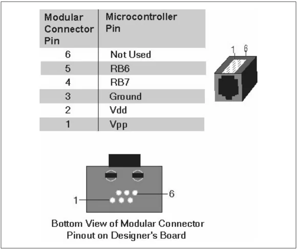
The following table shows how the modular connector pins on an application correspond to the microcontroller pins. This configuration provides the full MPLAB ICD 2 functionality.
Hardware Specifications
FIGURE A-1: MODULAR CONNECTOR PINOUT OF DESIGNER'S BOARD
A.3.2 Modular Plug Specification
- Manufacturer, Part Number – AMP Incorporated, 5-554710-3
- Distributor, Part Number – Digikey, A9117ND
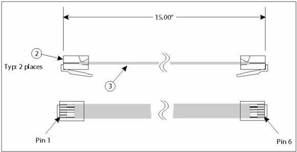
A.3.3 Modular Cable Specification
• Manufacturer, Part Number – Microchip Technology, 07-00024
Hardware Specifications
A.4 POWER SUPPLY
The MPLAB ICD 2 module requires a 9.0 V, 750 mA power supply. The demo board or your target application may also require an additional power supply if it is drawing too much power from the MPLAB ICD 2 module. The MPLAB ICD 2 module can power a demo board/target application of up to 200 mA for 5 VDC.
A power adapter is included in the following product kits:
| Part Number | Description | Includes these Components |
|---|---|---|
| DV164006 | MPLAB® ICD 2 Evaluation Kit | MPLAB ICD 2 module, USB, MPLAB ICD 2 interface and RS-232 cables, PICDEM 2 Plus demo board, power adapter, MPLAB IDE CD-ROM |
| DV164007 | MPLAB ICD 2 Module SW | MPLAB ICD 2 module, USB, MPLAB ICD 2 interface and RS-232 cables, power adapter, MPLAB IDE CD-ROM |
| AC162048 | RS-232 Desk Top Kit | Power adapter and RS-232 cable |
The power supply specifications for the MPLAB ICD 2 module and the PICDEM 2 Plus demo board are:
- DC power supply: 9 VDC @ 0.75A
- With barrel connector: ID = 2.5 mm, OD = 5.5 mm, barrel length = 10.0 mm, inside positive
ICD2PDF.book Page 132 Friday, November 9, 2007 3:21 PM
NOTES:
ICD2PDF.book Page 133 Friday, November 9, 2007 3:21 PM
MPLAB® ICD 2
MICROCHIP USER’S GUIDE
Index
A
- Abort ........ 72, 74
- Additional ........ 63 Advanced Breakpoint Dialog
- dsPIC30F Devices ........ 89
- dsPIC33F Devices ........ 91
- Extended PIC18F Devices ........ 85
- Extended PIC18F Devices V2 ........ 86
- PIC18F Devices ........ 84
- PIC24F Devices ........ 91
- Animate ........ 70
- Application Code ........ 102
- AVDD ........ 17, 102
- AVss ........ 17, 102
B
- Blank Check ........ 39, 74
- Blinking LED ........ 114
- Breakpoints ........ 35, 71
- Advanced ........ 84, 85, 86, 89, 91
- Setting ........ 53, 116
- BSR Register ........ 115
- Build-In Debug Circuitry ........ 68
C
- Calibration Data ........ 113, 116
- CALL FAST ........ 103, 115
- Capacitors ........ 18
- Circuits that Interfere with MPLAB ICD 2 ........ 18
- Code Protect ........ 20, 103, 112
- Communications ........ 27
- Configuration Bits ........ 20, 32, 49
- Connecting ........ 30, 31, 32, 43, 72, 74
- Connections ........ 16
- Creating a Hex File ........ 48
- Customer Notification Service ........ 8
- Customer Support ........ 9
D
Debug
- Executive ........ 23, 102, 111
- Registers ........ 24, 103
- Reserved Resources ........ 24
- Resources ........ 103 Debug Mode
- Requirements ........ 20
- Sequence of Operations ........ 21
- Debug Tool ........ 29
- Debugger Menu ........ 52
- Debugging ........ 34, 53
- Demo Board ........ 51
- Device Selection ........ 29
- Download ........ 72, 74
- Drivers Not Found ........ 112
- dsPIC Silicon Version Information ........ 32
E
- EEData ........ 113
- EEPROM ........ 36
- EEPROM Data Memory, Start Of ........ 65
- Environment Setup ........ 32
- Erase ........ 39, 73
- Erase All Before Programming ........ 50, 113
- Error LED ........ 115
- External Memory, ROMless Devices ........ 67
Index
F Fast
- Call ........ 103, 115
- Interrupts ........ 103
- Return ........ 115
- Firmware ........ 43, 99
- Firmware Upgrades ........ 63
- Frequently ........ 109
G
- Getting Started ........ 25
- GP1/RA1 ........ 114
- GPIO ........ 114
- Green Light ........ 29, 42
H
- Halt ........ 70
- Header Board ........ 24, 26, 109
- Specification ........ 6, 68
- Hex File ........ 36, 48, 64
- Hold in Reset ........ 74
- How MPLAB ICD 2 Works ........ 14
I
- ICD ........ 99
- Cable ........ 16
- Devices ........ 68
- Header Adapters ........ 109
- ICE Devices ........ 68
- ICE vs ICD ........ 14
- ICSP ........ 20, 24
- Installation ........ 27
- Interconnections ........ 16
- Internal Buffer Circuits ........ 100
- Internet Address ........ 7
- Interrupts ........ 114
- Fast ........ 103
- High Priority ........ 115
L
- Linker Script File ........ 65
- Loading Program and Debug Code ........ 51
- Low Voltage ........ 111
- LVP ........ 112
M
- MCLR ........ 74
- Microchip Internet Web Site ........ 7
- Modular Interface Cable ........ 16, 20, 26
- MPASM Assembler ........ 44
- MPLAB ........ 13
- mplab.exe ........ 28
O
- On-Chip Debug Circuitry ........ 68
- Operating System Upgrades ........ 63
- Oscillator, Target ........ 101
P
- PGC, PGD ........ 17, 109
- PIC18F452 ........ 41
- PICDEM 18R ........ 66
- PICDEM 2 Plus demo board ........ 41
- Port B ........ 114
- Power ........ 110
- Sequence ........ 30
- Target ........ 100
- Program ........ 71, 73
- Device for Debug ........ 34
- Mode ........ 24
- Tab, Settings Dialog ........ 50
- Programmer ........ 37
- Programming ........ 58
- Programming Options ........ 49
- Project ........ 33
- Project Wizard ........ 44
- Pull-ups ........ 18
Index
R
- Read ........ 71, 73
- Read a Device ........ 38
- Read EEPROM ........ 71
- Real-Time Execution ........ 35
- Red Light ........ 29
- Release from Reset ........ 74
- Reserved Resources ........ 24 Reset
- Hold in ........ 74
- Processor ........ 71
- Release from ........ 74
- Resistors ........ 18
- RETFIE ........ 115
- RETURN FAST ........ 115
- ROMless Devices ........ 65
- RS-232 ........ 26
- Run ........ 70
S
- Selecting Device and Development Mode ........ 42
- Self Test ........ 115
- Set Breakpoint ........ 53
- Setting Program and Debug Options ........ 48
- Setting Up Hardware and Software ........ 42
- Settings Dialog ........ 33
- Setup Wizard ........ 43, 81
- Shadow Stack ........ 103
- Single Stepping ........ 116
- Status Register ........ 115
- Step ........ 70
- Step-Mode Execution ........ 36
- System Components ........ 26
T
- Table Read Protect ........ 20, 103 Target
- Device ........ 99
- Oscillator ........ 101
- Power ........ 100
- Timers ........ 114, 116
- Toolbar Buttons ........ 52
- Troubleshooting ........ 97
- tut452.asm ........ 52
- Source Code ........ 59
- Tutorial ........ 41
U
- Updating Firmware ........ 43
- USB ........ 26
- Drivers ........ 98, 110
- Hub ........ 110
V
- VDD ........ 17
- Verify ........ 38, 73
W
- W Register ........ 115
- Warranty Registration ........ 5
- Watch Window ........ 55
- Watchdog Timer ........ 20
- Windows Device Manager ........ 110
- WWW Address ........ 7
Y
- Yellow Light ........ 29
ICD2PDF.book Page 139 Friday, November 9, 2007 3:21 PM
Index
NOTES:
ICD2PDF.book Page 140 Friday, November 9, 2007 3:21 PM
NOTES:
ICD2PDF.book Page 141 Friday, November 9, 2007 3:21 PM
Index
NOTES:
Worldwide Sales and Service
AMERICAS
Corporate Office
Tel: 480-792-7200
Atlanta
Tel: 678-957-9614
Boston
Tel: 774-760-0087
Chicago
Tel: 630-285-0071
Dallas
Tel: 972-818-7423
Detroit
Tel: 248-538-2250
Kokomo
Tel: 765-864-8360
Los Angeles
Tel: 949-462-9523
Santa Clara
Tel: 408-961-6444
Toronto
Tel: 905-673-0699
ASIA/PACIFIC
Hong Kong
Tel: 852-2401-1200
Australia - Sydney
Tel: 61-2-9868-6733
China - Beijing
Tel: 86-10-8528-2100
China - Chengdu
Tel: 86-28-8665-5511
China - Fuzhou
Tel: 86-591-8750-3506
China - Hong Kong SAR
Tel: 852-2401-1200
China - Qingdao
Tel: 86-532-8502-7355
China - Shanghai
Tel: 86-21-5407-5533
China - Shenyang
Tel: 86-24-2334-2829
China - Shenzhen
Tel: 86-755-8203-2660
China - Shunde
Tel: 86-757-2839-5507
China - Wuhan
Tel: 86-27-5980-5300
China - Xian
Tel: 86-29-8833-7250
India - Bangalore
Tel: 91-80-4182-8400
India - New Delhi
Tel: 91-11-4160-8631
India - Pune
Tel: 91-20-2566-1512
Japan - Yokohama
Tel: 81-45-471-6166
Korea - Gumi
Tel: 82-54-473-4301
Korea - Seoul
Tel: 82-2-554-7200
Malaysia - Penang
Tel: 60-4-646-8870
Philippines - Manila
Tel: 63-2-634-9065
Singapore
Tel: 65-6334-8870
Taiwan - Hsin Chu
Tel: 886-3-572-9526
Taiwan - Kaohsiung
Tel: 886-7-536-4818
Taiwan - Taipei
Tel: 886-2-2500-6610
Thailand - Bangkok
Tel: 66-2-694-1351
EUROPE
Austria - Wels
Tel: 43-7242-2244-39
Denmark - Copenhagen
Tel: 45-4450-2828
France - Paris
Tel: 33-1-69-53-63-20
Germany - Munich
Tel: 49-89-627-144-0
Italy - Milan
Tel: 39-0331-742611
Netherlands - Drunen
Tel: 31-416-690399
Spain - Madrid
Tel: 34-91-708-08-90
UK - Wokingham
Tel: 44-118-921-5869
DS51331C-page 142
© 2007 Microchip Technology