ICD2PDF.book Page i Friday, November 9, 2007 3:21 PM
MICROCHIP
MPLAB® ICD 2
In-Circuit Debugger
User’s Guide
© 2007 Microchip Technology Inc. DS51331C

Note the following details of the code protection feature on Microchip devices:
- Microchip products meet the specification contained in their particular Microchip Data Sheet.
- Microchip believes that its family of products is one of the most secure families of its kind on the market today, when used in the intended manner and under normal conditions.
- There are dishonest and possibly illegal methods used to breach the code protection feature. All of these methods, to our knowledge, require using the Microchip products in a manner outside the operating specifications contained in Microchip’s Data Sheets. Most likely, the person doing so is engaged in theft of intellectual property.
- Microchip is willing to work with the customer who is concerned about the integrity of their code.
Neither Microchip nor any other semiconductor manufacturer can guarantee the security of their code. Code protection does not mean that we are guaranteeing the product as "unbreakable."
Code protection is constantly evolving. We at Microchip are committed to continuously improving the code protection features of our products. Attempts to break Microchip’s code protection feature may be a violation of the Digital Millennium Copyright Act. If such acts allow unauthorized access to your software or other copyrighted work, you may have a right to sue for relief under that Act.
Information contained in this publication regarding device applications and the like is provided only for your convenience and may be superseded by updates. It is your responsibility to ensure that your application meets with your specifications. MICROCHIP MAKES NO REPRESENTATIONS OR WARRANTIES OF ANY KIND WHETHER EXPRESS OR IMPLIED, WRITTEN OR ORAL, STATUTORY OR OTHERWISE, RELATED TO THE INFORMATION, INCLUDING BUT NOT LIMITED TO ITS CONDITION, QUALITY, PERFORMANCE, MERCHANTABILITY OR FITNESS FOR PURPOSE. Microchip disclaims all liability arising from this information and its use. Use of Microchip devices in life support and/or safety applications is entirely at the buyer’s risk, and the buyer agrees to defend, indemnify and hold harmless Microchip from any and all damages, claims, suits, or expenses resulting from such use. No licenses are conveyed, implicitly or otherwise, under any Microchip intellectual property rights.
Trademarks
The Microchip name and logo, the Microchip logo, Accuron, dsPIC, KEELOQ, KEELOQ logo, microID, MPLAB, PIC, PICmicro, PICSTART, PRO MATE, rfPIC and SmartShunt are registered trademarks of Microchip Technology Incorporated in the U.S.A. and other countries.
AmpLab, FilterLab, Linear Active Thermistor, Migratable Memory, MXDEV, MXLAB, SEEVAL, SmartSensor and The Embedded Control Solutions Company are registered trademarks of Microchip Technology Incorporated in the U.S.A.
Analog-for-the-Digital Age, Application Maestro, CodeGuard, dsPICDEM, dsPICDEM.net, dsPICworks, ECAN, ECONOMONITOR, FanSense, FlexROM, fuzzyLAB, In-Circuit Serial Programming, ICSP, ICEPIC, Mindi, MiWi, MPASM, MPLAB Certified logo, MPLIB, MPLINK, Pickit, PICDEM, PICDEM.net, PICLAB, PICtail, PowerCal, PowerInfo, PowerMate, PowerTool, REAL ICE, rfLAB, Select Mode, Smart Serial, SmartTel, Total Endurance, UNI/O, WiperLock and ZENA are trademarks of Microchip Technology Incorporated in the U.S.A. and other countries.
SQTP is a service mark of Microchip Technology Incorporated in the U.S.A.
All other trademarks mentioned herein are property of their respective companies.
© 2007, Microchip Technology Incorporated, Printed in the U.S.A., All Rights Reserved.
Printed on recycled paper.
DS51331C-page ii © 2007 Microchip Technology Inc.
ICD2PDF.book Page iii Friday, November 9, 2007 3:21 PM
MPLAB® ICD 2
MICROCHIP USER’S GUIDE
Table of Contents
- Preface ........ 1 Part 1 –Operation
Chapter 1. MPLAB ICD 2 Overview
- 1.1 Introduction ........ 13
- 1.2 What is MPLAB ICD 2? ........ 13
- 1.3 How MPLAB ICD 2 Helps You ........ 14
- 1.4 How MPLAB ICD 2 Works ........ 14
- 1.5 Resources Used By MPLAB ICD 2 ........ 24
Chapter 2. Getting Started
- 2.1 Introduction ........ 25
- 2.2 MPLAB ICD 2 System Components ........ 26 2.3 Installing and Configuring MPLAB IDE for
- MPLAB ICD 2 ........ 27
- 2.4 Applying Power ........ 30
- 2.5 Connection Options ........ 32
- 2.6 Setting Up the Environment ........ 32
- 2.7 MPLAB ICD 2 Development Process ........ 34
Chapter 3. MPLAB ICD 2 Tutorial
- 3.1 Introduction ........ 41
- 3.2 Setting Up The Environment ........ 42
- 3.3 Running the Project Wizard ........ 44
- 3.4 Viewing the Project ........ 47
- 3.5 Creating a Hex File ........ 48
© 2007 Microchip Technology Inc. DS51331C-page iii
- 3.6 Setting Debug Options ........ 49
- 3.7 Setting Up the Demo Board ........ 51
- 3.8 Loading Program Code For Debugging ........ 51
- 3.9 Running TUT452 ........ 52
- 3.10 Debugging TUT452 ........ 53
- 3.11 Programming the Application ........ 58
- 3.12 TUT452 Main Routine and Source Code ........ 59
Chapter 4. Additional Topics
- 4.1 Introduction ........ 63 4.2 Upgrading the MPLAB ICD 2 Firmware
- (Operating System) ........ 63
- 4.3 Creating/Loading a Hex File ........ 64
- 4.4 Special Linker Script Files ........ 65
- 4.5 ROMless Device Considerations ........ 65
- 4.6 ICD/ICE Devices ........ 68
Chapter 5. ICD Function Summary
- 5.1 Introduction ........ 69
- 5.2 Debugging Functions ........ 69
- 5.3 Programming Functions ........ 73
- 5.4 Settings Dialog ........ 75
- 5.5 Setup Wizard ........ 81
- 5.6 Advanced Breakpoints Dialog ........ 84
Part 2 –Troubleshooting
Chapter 6. Troubleshooting Tips
- 6.1 Introduction ........ 97
- 6.2 Link: PC to MPLAB ICD 2 Communications ........ 98
- 6.3 Link: MPLAB ICD 2 Firmware ........ 99
DS51331C-page iv © 2007 Microchip Technology
6.4 Link: MPLAB ICD 2 to Target
- PIC MCU Device ........ 99
- 6.5 Link: Target Power ........ 100
- 6.6 Link: Target Oscillator ........ 101
- 6.7 Link: Application Code ........ 102
- 6.8 Link: Debug Executive ........ 102
- 6.9 Link: In-Circuit Debug Registers ........ 103
- 6.10 Link: In-Circuit Debug Resources ........ 103
Chapter 7. Self Test
- 7.1 Introduction ........ 105
- 7.2 Target VDD ........ 105
- 7.3 Module VPP ........ 106
- 7.4 MCLR = GND ........ 106
- 7.5 MCLR = VDD ........ 107
- 7.6 MCLR = VPP ........ 107
- 7.7 Failed Self Test Error – VPP/VDD High/Low ........ 108
Chapter 8. General Troubleshooting
- 8.1 Introduction ........ 109
- 8.2 Frequently Asked Questions ........ 109
- 8.3 Common Communication Problems ........ 117
- 8.4 Common Problems ........ 122
- 8.5 Error and Warning Messages ........ 125
- 8.6 Limitations ........ 125
Appendix A. Hardware Specifications
-
A.1 Introduction ........ 127
-
A.2 MPLAB ICD 2 Module ........ 127
-
A.3 Modular Cable and Connector ........ 128
-
A.4 Power Supply ........ 131
-
Index ........ 133
© 2007 Microchip Technology Inc. DS51331C-page v
ICD2PDF.book Page vi Friday, November 9, 2007 3:21 PM
NOTES:
DS51331C-page vi © 2007 Microchip Technology
ICD2PDF.book Page 1 Friday, November 9, 2007 3:21 PM
MICROCHIP
MPLAB® ICD 2
USER’S GUIDE
Preface
NOTICE TO CUSTOMERS
All documentation becomes dated, and this manual is no exception. Microchip tools and documentation are constantly evolving to meet customer needs, so some actual dialogs and/or tool descriptions may differ from those in this document. Please refer to our web site (www.microchip.com) to obtain the latest documentation available.
Documents are identified with a “DS” number. This number is located on the bottom of each page, in front of the page number. The numbering convention for the DS number is “DSXXXXXA”, where “XXXXX” is the document number and “A” is the revision level of the document.
For the most up-to-date information on development tools, see the MPLAB® IDE on-line help. Select the Help menu, and then Topics to open a list of available on-line help files.
ICD2PDF.book Page 2 Friday, November 9, 2007 3:21 PM
INTRODUCTION
The support information discussed here can help you when using the MPLAB ICD 2 in-circuit debugger.
Topics covered in this chapter:
• Document Layout • Conventions Used in this Guide • Warranty Registration • Reference Documents • The Microchip Web Site • Development Systems Customer Change Notification Service • Customer Support
Preface
DOCUMENT LAYOUT
This document describes how to use the MPLAB ICD 2 as a development tool to emulate and debug firmware on a target board. The manual layout is as follows:
• Part 1 – Operation
- Chapter 1. MPLAB ICD 2 Overview – explains the MPLAB ICD 2, how it helps you and how it works.
- Chapter 2. Getting Started – describes the system components, provides installation and configuration instructions, explains how to set up the environment and discusses the development process.
- Chapter 3. MPLAB ICD 2 Tutorial – provides a tutorial using the Project Wizard.
- Chapter 4. Additional Topics – discusses upgrading firmware, using hex files and linker scripts, and provides information on ROMless devices and ICD/ICE devices.
- Chapter 5. ICD Function Summary – describes all the ICD menus, toolbars and dialogs. • Part 2 – Troubleshooting
- Chapter 6. Troubleshooting Tips – describes the chain of functionality.
- Chapter 7. Self-Test – discusses the various self-test features.
- Chapter 8. General Troubleshooting – provides answers to frequently asked questions, discusses common problems, and provides error and warning messages. • Appendix A. Hardware Specifications – contains information on the MPLAB ICD 2 module, the cable and connector, and power supply.
CONVENTIONS USED IN THIS GUIDE
This manual uses the following documentation conventions:
DOCUMENTATION CONVENTIONS
Preface
DOCUMENTATION CONVENTIONS (CONTINUED)
WARRANTY REGISTRATION
Please complete the enclosed Warranty Registration Card and mail it promptly. Sending in the Warranty Registration Card entitles users to receive new product updates. Interim software releases are available at the Microchip web site.
MPLAB® ICD 2 User’s Guide
REFERENCE DOCUMENTS
This document describes how to use MPLAB ICD 2. Other useful documents are listed below.
MPLAB® ICD 2 Design Advisory (DS51566) Please read this first! Contains important information about using the MPLAB ICD 2 with your target design.
Readme for MPLAB ICD 2 For the latest information on using MPLAB ICD 2, read the Readme for MPLAB ICD 2.txt file (an ASCII text file) in the MPLAB IDE directory. The README file contains update information and known issues that may not be included in this on-line help file.
Using MPLAB® ICD 2 (DS51265) A poster showing the various ways you can set up MPLAB ICD 2 hardware.
Header Board Specification (DS51292) A small booklet describing how to install and use MPLAB ICD 2 headers. Headers are used to better debug selected devices using special -ICD/ICE device versions, without the loss of pins or resources.
Universal Programming Module Instruction Sheet (DS51280) A sheet describing how to use the UPM.
Preface
THE MICROCHIP WEB SITE
Microchip provides online support via our web site at www.microchip.com. This web site is used as a means to make files and information easily available to customers. Accessible by using your favorite Internet browser, the web site contains the following information:
- Product Support – Data sheets and errata, application notes and sample programs, design resources, user’s guides and hardware support documents, latest software releases and archived software
- General Technical Support – Frequently Asked Questions (FAQs), technical support requests, online discussion groups, Microchip consultant program member listing
- Business of Microchip – Product selector and ordering guides, latest Microchip press releases, listing of seminars and events, listings of Microchip sales offices, distributors and factory representatives
DEVELOPMENT SYSTEMS CUSTOMER CHANGE NOTIFICATION SERVICE
Microchip’s customer notification service helps keep customers current on Microchip products. Subscribers will receive e-mail notification whenever there are changes, updates, revisions or errata related to a specified product family or development tool of interest.
To register, access the Microchip web site at www.microchip.com, click on Customer Change Notification and follow the registration instructions.
The Development Systems product group categories are:
- Compilers – The latest information on Microchip C compilers and other language tools. These include the MPLAB C18 and MPLAB C30 C compilers; MPASM™ and MPLAB ASM30 assemblers; MPLINK™ and MPLAB LINK30 object linkers; and MPLIB™ and MPLAB LIB30 object librarians.
- Emulators – The latest information on Microchip in-circuit emulators. This includes the MPLAB ICE 2000 and MPLAB ICE 4000.
- In-Circuit Debuggers – The latest information on the Microchip in-circuit debugger, MPLAB ICD 2.
- MPLAB IDE – The latest information on Microchip MPLAB IDE, the Windows® Integrated Development Environment for development systems tools. This list is focused on the MPLAB IDE, MPLAB SIM simulator, MPLAB IDE Project Manager and general editing and debugging features.
- Programmers – The latest information on Microchip programmers. These include the MPLAB PM3 and PRO MATE® II device programmers and the PICSTART® Plus and PICkit™ 1 development programmers.
Preface
CUSTOMER SUPPORT
Users of Microchip products can receive assistance through several channels:
- Distributor or Representative
- Local Sales Office
- Field Application Engineer (FAE)
- Technical Support
Customers should contact their distributor, representative or field application engineer (FAE) for support. Local sales offices are also available to help customers. A listing of sales offices and locations is included in the back of this document.
Technical support is available through the web site at: http://support.microchip.com
ICD2PDF.book Page 10 Friday, November 9, 2007 3:21 PM
NOTES:
ICD2PDF.book Page 11 Friday, November 9, 2007 3:21 PM
MPLAB® ICD 2
MICROCHIP USER’S GUIDE
Part 1 – Operation
- Chapter 1. MPLAB ICD 2 Overview ........ 13
- Chapter 2. Getting Started ........ 25
- Chapter 3. MPLAB ICD 2 Tutorial ........ 41
- Chapter 4. Additional Topics ........ 63
- Chapter 5. ICD Function Summary ........ 69

ICD2PDF.book Page 12 Friday, November 9, 2007 3:21 PM
NOTES:
ICD2PDF.book Page 13 Friday, November 9, 2007 3:21 PM
MICROCHIP
MPLAB® ICD 2
USER’S GUIDE
Chapter 1. MPLAB ICD 2 Overview
1.1 INTRODUCTION
An overview of the MPLAB ICD 2 development tool is given here. MPLAB ICD 2 is defined and its operation explained. Additionally, device resources used during debugging are listed.
Topics covered in this chapter are:
- What is MPLAB ICD 2?
- How MPLAB ICD 2 Helps You
- How MPLAB ICD 2 Works
- Resources Used By MPLAB ICD 2
1.2 WHAT IS MPLAB ICD 2?
The MPLAB ICD 2 is a low-cost in-circuit debugger (ICD) and in-circuit serial programmer.
MPLAB ICD 2 is intended to be used as an evaluation, debugging and programming aid in a laboratory environment.
The MPLAB ICD 2 offers these features:
- Real-time and single-step code execution
- Breakpoints, Register and Variable Watch/Modify
- In-circuit debugging
- Target VDD monitor
- Diagnostic LEDs
- MPLAB IDE user interface
- RS-232 serial or USB interface to a host PC
1.3 HOW MPLAB ICD 2 HELPS YOU
The MPLAB ICD 2 allows you to:
• Debug your source code in your own application
• Debug your hardware in real-time
• Program a supported device using Microchip's ICSP™ protocol
1.4 HOW MPLAB ICD 2 WORKS
A simplified description of how MPLAB ICD 2 works is provided here. It is intended to provide enough information so a target board can be designed that is compatible with MPLAB ICD 2 for both programming and debugging operations. The basic theory of programming and in-circuit debugging is described so that problems, if encountered, are quickly resolved.
This section provides an overview of MPLAB ICD 2, followed by a description of MPLAB ICD 2 programming and debugging modes. The following topics are covered:
• ICD vs. ICE
• Modular Interface Connections
• Circuits That Will Prevent MPLAB ICD 2 From Functioning
• Debug Mode
• Requirements For Debug Mode
• Debug Reserved Resources
• Programmer Mode
1.4.1 ICD vs. ICE
The in-circuit debugger (ICD) is a cost-efficient alternative to an in-circuit emulator (ICE). It can do many things that were previously done only with more expensive hardware, but the cost benefits come with a trade-off of some of the conveniences of an in-circuit emulator. If users are willing to design their application to be ICD compatible, they can enjoy the benefits of a low-cost hardware debugger.
MPLAB ICD 2 Overview
As opposed to an ICE, some of the requirements of the in-circuit debugger are:
- The in-circuit debugger requires exclusive use of some hardware and software resources of the target.
- The target PIC® MCU must have a functioning clock and be running.
- The ICD can debug only when all the links in the system are fully functional.
An emulator provides memory and a clock, and can run code – even without being connected to the target application board. During the development and debugging cycle, an ICE provides the most power to get the system fully functional, whereas an ICD may not be able to debug at all if the application does not run. On the other hand, an in-circuit debug connector can be placed on the application board and connected to an ICD even after the system has been produced, allowing easy testing, debugging and reprogramming of the application. Even though an ICD has some drawbacks in comparison to an ICE, in this situation it has some distinct advantages:
- A connection to the application after it has been produced does not require extraction of the microcontroller in order to insert an ICE probe.
- The ICD can reprogram the firmware in the target application without any other connections or equipment.
Note: An ICE uses custom hardware to emulate the target microcontroller. An ICD uses hardware on the target microcontroller to do some of the functions of an ICE. An ICD also employs software running on the target to do ICE-like functions and, as a result, relies upon the target microcontroller for some memory space, CPU control, stack storage and I/O pins for communication.
1.4.2 Modular Interface Connections
MPLAB ICD 2 is connected to the target PIC MCU with the modular interface cable, which is a six conductor cable. The pin numbering for the MPLAB ICD 2 connector is shown from the bottom of the target PC board in Figure 1-1.
Note: The ICD cable has mirror imaged connections on each end, and connections on the MPLAB ICD 2 module are the opposite of connections shown here.
FIGURE 1-1: PIN NUMBERING FOR MODULAR CONNECTOR
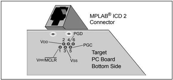
Figure 1-2 shows the interconnections of the MPLAB ICD 2 to the modular connector on the target board. There are six pins on the ICD connector, but only five are used. The diagram also shows the wiring from the connector to the PIC MCU device on the target PC board. A pull-up resistor (usually around 10k Ohm) is recommended to be connected from the VPP/MCLR line to VDD so that the line may be strobed low to reset the PIC MCU.
MPLAB ICD 2 Overview
FIGURE 1-2: MPLAB® ICD 2 CONNECTIONS TO TARGET BOARD
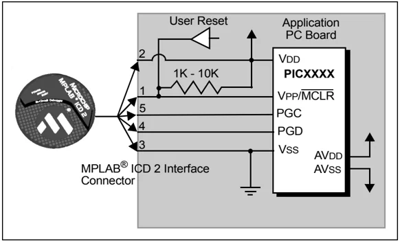
Although pin 2 (VDD) can supply a limited amount of power to the target application under certain conditions, for the purposes of these descriptions, pins 2 and 3 (VSS) are omitted. They are shown on the diagram for completeness, but in the following descriptions only three lines are active and relevant to core MPLAB ICD 2 operation: VPP/MCLR, PGC and PGD.
Note: In the following discussions, VDD is ignored. But be aware that the target VDD is also used to power the output drivers in MPLAB ICD 2. This allows level translation for target low-voltage operation. If MPLAB ICD 2 does not have voltage on its VDD line (pin 2 of the ICD connector), either from power being supplied to the target by MPLAB ICD 2 or from a separate target power supply, it will not operate.
Not all PIC MCUs have the AVDD and AVSS lines, but if they are present on the target PIC MCU, all must be connected in order for MPLAB ICD 2 to operate.
The interconnection is very simple, any problems experienced are often caused by other connections or components on these critical lines that interfere with the operation of MPLAB ICD 2, as discussed in Section 1.4.3 “Circuits That Will Prevent MPLAB ICD 2 From Functioning”.
1.4.3 Circuits That Will Prevent MPLAB ICD 2 From Functioning
Figure 1-3 shows the active MPLAB ICD 2 lines with some components that will prevent MPLAB ICD 2 from functioning:
FIGURE 1-3: IMPROPER CIRCUIT COMPONENTS
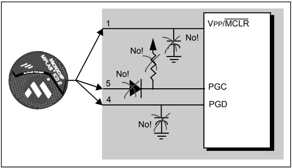
Specifically, these guidelines must be followed:
- No pull-ups on PGC/PGD – they will divide the voltage levels, since these lines have 4.7K\Omega pull-down resistors in MPLAB ICD 2.
- No capacitors on PGC/PGD – they will prevent fast transitions on data and clock lines during programming and debug communications.
- No capacitors on \overlineMCLR – they will prevent fast transitions of VPP. A simple pull-up resistor is generally sufficient.