28/40/44-Pin Enhanced Flash Microcontrollers
Devices Included in this Data Sheet:
- PIC16F873A
- PIC16F874A
- PIC16F876A
- PIC16F877A
High-Performance RISC CPU:
- Only 35 single-word instructions to learn
- All single-cycle instructions except for program branches, which are two-cycle
- Operating speed: DC – 20 MHz clock input DC – 200 ns instruction cycle
- Up to 8K x 14 words of Flash Program Memory, Up to 368 x 8 bytes of Data Memory (RAM), Up to 256 x 8 bytes of EEPROM Data Memory
- Pinout compatible to other 28-pin or 40/44-pin PIC16CXXX and PIC16FXXX microcontrollers
Peripheral Features:
- Timer0: 8-bit timer/counter with 8-bit prescaler
- Timer1: 16-bit timer/counter with prescaler, can be incremented during Sleep via external crystal/clock
- Timer2: 8-bit timer/counter with 8-bit period register, prescaler and postscaler
- Two Capture, Compare, PWM modules
- Capture is 16-bit, max. resolution is 12.5 ns
- Compare is 16-bit, max. resolution is 200 ns
- PWM max. resolution is 10-bit
- Synchronous Serial Port (SSP) with SPI (Master mode) and I²C™ (Master/Slave)
- Universal Synchronous Asynchronous Receiver Transmitter (USART/SCI) with 9-bit address detection
- Parallel Slave Port (PSP) – 8 bits wide with external RD, WR and CS controls (40/44-pin only)
- Brown-out detection circuitry for Brown-out Reset (BOR)
Analog Features:
- 10-bit, up to 8-channel Analog-to-Digital Converter (A/D)
- Brown-out Reset (BOR)
- Analog Comparator module with:
- Two analog comparators
- Programmable on-chip voltage reference (VREF) module
- Programmable input multiplexing from device inputs and internal voltage reference
- Comparator outputs are externally accessible
Special Microcontroller Features:
- 100,000 erase/write cycle Enhanced Flash program memory typical
- 1,000,000 erase/write cycle Data EEPROM memory typical
- Data EEPROM Retention > 40 years
- Self-reprogrammable under software control
- In-Circuit Serial Programming™ (ICSP™) via two pins
- Single-supply 5V In-Circuit Serial Programming
- Watchdog Timer (WDT) with its own on-chip RC oscillator for reliable operation
- Programmable code protection
- Power saving Sleep mode
- Selectable oscillator options
- In-Circuit Debug (ICD) via two pins
CMOS Technology:
- Low-power, high-speed Flash/EEPROM technology
- Fully static design
- Wide operating voltage range (2.0V to 5.5V)
- Commercial and Industrial temperature ranges
- Low-power consumption
| Device | Program Memory | Data SRAM (Bytes) | EEPROM (Bytes) | I/O | 10-bit A/D (ch) | CCP (PWM) | MSSP | USART | Timers 8/16-bit | Comparators | ||
|---|---|---|---|---|---|---|---|---|---|---|---|---|
| Bytes | # Single Word Instructions | SPI | Master I²C | |||||||||
| PIC16F873A | 7.2K | 4096 | 192 | 128 | 22 | 5 | 2 | Yes | Yes | Yes | 2/1 | 2 |
| PIC16F874A | 7.2K | 4096 | 192 | 128 | 33 | 8 | 2 | Yes | Yes | Yes | 2/1 | 2 |
| PIC16F876A | 14.3K | 8192 | 368 | 256 | 22 | 5 | 2 | Yes | Yes | Yes | 2/1 | 2 |
| PIC16F877A | 14.3K | 8192 | 368 | 256 | 33 | 8 | 2 | Yes | Yes | Yes | 2/1 | 2 |

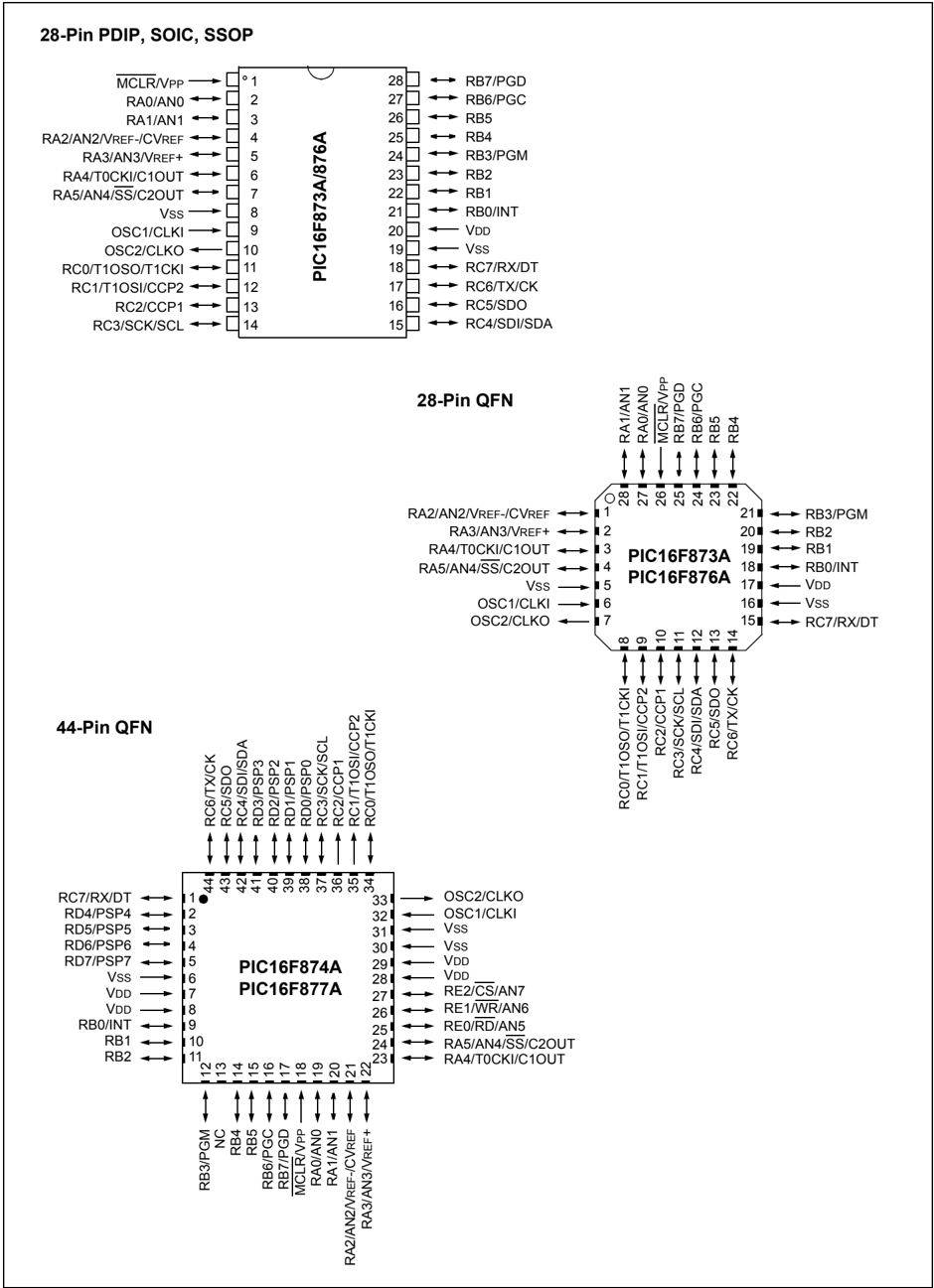
Pin Diagrams
28-Pin PDIP, SOIC, SSOP
MCLR/VPP → 1 ○ 28 ← RB7/PGD RA0/AN0 ← 2 27 ← RB6/PGC RA1/AN1 ← 3 26 ← RB5 RA2/AN2/VREF-/CVREF ← 4 25 ← RB4 RA3/AN3/VREF+ ← 5 24 ← RB3/PGM RA4/T0CKI/C1OUT ← 6 23 ← RB2 RA5/AN4/SS/C2OUT ← 7 22 ← RB1 Vss ← 8 21 ← RB0/INT OSC1/CLKI ← 9 20 ← VDD OSC2/CLKO ← 10 19 ← Vss RC0/T1OSO/T1CKI ← 11 18 ← RC7/RX/DT RC1/T1OSI/CCP2 ← 12 17 ← RC6/TX/CK RC2/CCP1 ← 13 16 ← RC5/SDO RC3/SCK/SCL ← 14 15 ← RC4/SDI/SDA
28-Pin QFN
RA1/AN1 ↑ 28 ○ 21 ← RB3/PGM RA0/AN0 ↑ 27 20 ← RB2 MCLR/Vpp ↓ 26 19 ← RB1 RB7/PGD ↑ 25 18 ← RB0/INT RB6/PGC ↑ 24 17 ← VDD RB5 ↑ 23 16 ← Vss RB4 ↑ 22 15 ← RC7/RX/DT
RA2/AN2/VREF-/CVREF ← 1 14 ← RC6/TX/CK RA3/AN3/VREF+ ← 2 13 ← RC5/SDO RA4/T0CKI/C1OUT ← 3 12 ← RC4/SDI/SDA RA5/AN4/SS/C2OUT ← 4 11 ← RC3/SCK/SCL Vss ← 5 10 ← RC2/CCP1 OSC1/CLKI ← 6 9 ← RC1/T1OSI/CCP2 OSC2/CLKO ← 7 8 ← RC0/T1OSO/T1CKI
44-Pin QFN
RC7/RX/DT ← 1 ● 44 ← RC6/TX/CK RD4/PSP4 ← 2 43 ← RC5/SDO RD5/PSP5 ← 3 42 ← RC4/SDI/SDA RD6/PSP6 ← 4 41 ← RD3/PSP3 RD7/PSP7 ← 5 40 ← RD2/PSP2 Vss ← 6 39 ← RD1/PSP1 VDD ← 7 38 ← RD0/PSP0 VDD ← 8 37 ← RC3/SCK/SCL RB0/INT ← 9 36 ← RC2/CCP1 RB1 ← 10 35 ← RC1/T1OSI/CCP2 RB2 ← 11 34 ← RC0/T1OSO/T1CKI
RB3/PGM ↑ 12 33 → OSC2/CLKO NC ↑ 13 32 → OSC1/CLKI RB4 ↑ 14 31 → Vss RB5 ↑ 15 30 → Vss RB6/PGC ↑ 16 29 → VDD RB7/PGD ↑ 17 28 → VDD MCLR/Vpp ↑ 18 27 → RE2/CS/AN7 RA0/AN0 ↑ 19 26 → RE1/WR/AN6 RA1/AN1 ↑ 20 25 → RE0/RD/AN5 RA2/AN2/VREF-/CVREF ↑ 21 24 → RA5/AN4/SS/C2OUT RA3/AN3/VREF+ ↑ 22 23 → RA4/T0CKI/C1OUT
Pin Diagrams (Continued)
40-Pin PDIP
MCLR/VPP \rightarrow 1 RA0/AN0 \leftrightarrow 2 RA1/AN1 \leftrightarrow 3 RA2/AN2/VREF-/CVREF \leftrightarrow 4 RA3/AN3/VREF+ \leftrightarrow 5 RA4/T0CKI/C1OUT \leftrightarrow 6 RA5/AN4/SS/C2OUT \leftrightarrow 7 RE0/RD/AN5 \leftrightarrow 8 RE1/WR/AN6 \leftrightarrow 9 RE2/CS/AN7 \leftrightarrow 10 VDD \rightarrow 11 VSS \leftarrow 12 OSC1/CLKI \leftarrow 13 OSC2/CLKO \rightarrow 14 RC0/T1OSO/T1CKI \leftrightarrow 15 RC1/T1OSI/CCP2 \leftrightarrow 16 RC2/CCP1 \leftrightarrow 17 RC3/SCK/SCL \leftrightarrow 18 RD0/PSP0 \leftrightarrow 19 RD1/PSP1 \leftrightarrow 20
PIC16F874A/877A
40 \leftarrow RB7/PGD 39 \leftarrow RB6/PGC 38 \leftarrow RB5 37 \leftarrow RB4 36 \leftarrow RB3/PGM 35 \leftarrow RB2 34 \leftarrow RB1 33 \leftarrow RB0/INT 32 \leftarrow VDD 31 \leftarrow VSS 30 \leftarrow RD7/PSP7 29 \leftarrow RD6/PSP6 28 \leftarrow RD5/PSP5 27 \leftarrow RD4/PSP4 26 \leftarrow RC7/RX/DT 25 \leftarrow RC6/TX/CK 24 \leftarrow RC5/SDO 23 \leftarrow RC4/SDI/SDA 22 \leftarrow RD3/PSP3 21 \leftarrow RD2/PSP2
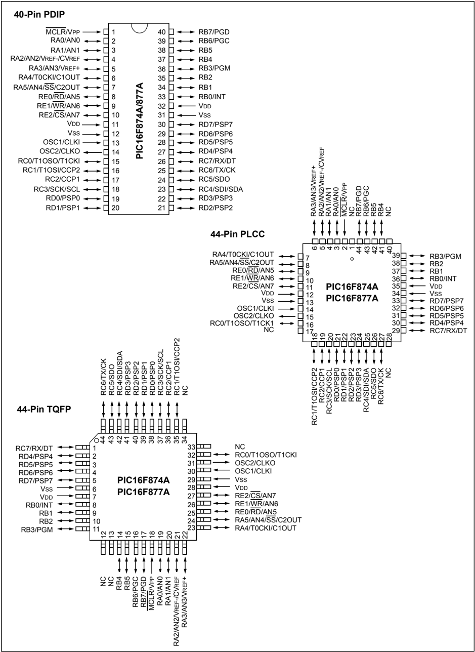
44-Pin PLCC
RA4/T0CKI/C1OUT \leftrightarrow 7 RA5/AN4/SS/C2OUT \leftrightarrow 8 RE0/RD/AN5 \leftrightarrow 9 RE1/WR/AN6 \leftrightarrow 10 RE2/CS/AN7 \leftrightarrow 11 VDD \rightarrow 12 VSS \leftarrow 13 OSC1/CLKI \leftarrow 14 OSC2/CLKO \rightarrow 15 RC0/T1OSO/T1CKI \leftrightarrow 16 NC \leftrightarrow 17
PIC16F874A PIC16F877A
RA3/AN3/VREF+ \updownarrow 6 RA2/AN2/VREF-/CVREF \updownarrow 5 RA1/AN1 \updownarrow 4 RA0/AN0 \updownarrow 3 MCLR/VPP \downarrow 2 NC \downarrow 1 RB7/PGD \updownarrow 44 RB6/PGC \updownarrow 43 RB5 \updownarrow 42 RB4 \updownarrow 41 NC \updownarrow 40
39 \leftarrow RB3/PGM 38 \leftarrow RB2 37 \leftarrow RB1 36 \leftarrow RB0/INT 35 \leftarrow VDD 34 \leftarrow VSS 33 \leftarrow RD7/PSP7 32 \leftarrow RD6/PSP6 31 \leftarrow RD5/PSP5 30 \leftarrow RD4/PSP4 29 \leftarrow RC7/RX/DT
RC1/T1OSI/CCP2 \updownarrow 18 RC2/CCP1 \updownarrow 19 RC3/SCK/SCL \updownarrow 20 RD0/PSP0 \updownarrow 21 RD1/PSP1 \updownarrow 22 RD2/PSP2 \updownarrow 23 RD3/PSP3 \updownarrow 24 RC4/SDI/SDA \updownarrow 25 RC5/SDO \updownarrow 26 RC6/TX/CK \updownarrow 27 NC \updownarrow 28
44-Pin TQFP
RC7/RX/DT \leftrightarrow 1 RD4/PSP4 \leftrightarrow 2 RD5/PSP5 \leftrightarrow 3 RD6/PSP6 \leftrightarrow 4 RD7/PSP7 \leftrightarrow 5 VSS \leftarrow 6 VDD \rightarrow 7 RB0/INT \leftrightarrow 8 RB1 \leftrightarrow 9 RB2 \leftrightarrow 10 RB3/PGM \leftrightarrow 11
PIC16F874A PIC16F877A
RC6/TX/CK \uparrow 44 RC5/SDO \uparrow 43 RC4/SDI/SDA \uparrow 42 RD3/PSP3 \uparrow 41 RD2/PSP2 \uparrow 40 RD1/PSP1 \uparrow 39 RD0/PSP0 \uparrow 38 RC3/SCK/SCL \uparrow 37 RC2/CCP1 \uparrow 36 RC1/T1OSI/CCP2 \uparrow 35 NC \uparrow 34
NC \leftarrow 33 RC0/T1OSO/T1CKI \leftrightarrow 32 OSC2/CLKO \rightarrow 31 OSC1/CLKI \leftarrow 30 VSS \leftarrow 29 VDD \rightarrow 28 RE2/CS/AN7 \leftrightarrow 27 RE1/WR/AN6 \leftrightarrow 26 RE0/RD/AN5 \leftrightarrow 25 RA5/AN4/SS/C2OUT \leftrightarrow 24 RA4/T0CKI/C1OUT \leftrightarrow 23
NC \updownarrow 12 NC \updownarrow 13 RB5 \updownarrow 14 RB6/PGC \updownarrow 15 RB7/PGD \updownarrow 16 MCLR/VPP \downarrow 17 RA0/AN0 \updownarrow 18 RA1/AN1 \updownarrow 19 RA2/AN2/VREF-/CVREF \updownarrow 20 RA3/AN3/VREF+ \updownarrow 21
Table of Contents
- 1.0 Device Overview ........ 5
- 2.0 Memory Organization ........ 15
- 3.0 Data EEPROM and Flash Program Memory ........ 33
- 4.0 I/O Ports ........ 41
- 5.0 Timer0 Module ........ 53
- 6.0 Timer1 Module ........ 57
- 7.0 Timer2 Module ........ 61
- 8.0 Capture/Compare/PWM Modules ........ 63
- 9.0 Master Synchronous Serial Port (MSSP) Module ........ 71
- 10.0 Addressable Universal Synchronous Asynchronous Receiver Transmitter (USART) ........ 111
- 11.0 Analog-to-Digital Converter (A/D) Module ........ 127
- 12.0 Comparator Module ........ 135
- 13.0 Comparator Voltage Reference Module ........ 141
- 14.0 Special Features of the CPU ........ 143
- 15.0 Instruction Set Summary ........ 159
- 16.0 Development Support ........ 167
- 17.0 Electrical Characteristics ........ 173
- 18.0 DC and AC Characteristics Graphs and Tables ........ 197
- 19.0 Packaging Information ........ 209
- Appendix A: Revision History ........ 219
- Appendix B: Device Differences ........ 219
- Appendix C: Conversion Considerations ........ 220
- Index ........ 221
- On-Line Support ........ 229
- Systems Information and Upgrade Hot Line ........ 229
- Reader Response ........ 230
- PIC16F87XA Product Identification System ........ 231
TO OUR VALUED CUSTOMERS
It is our intention to provide our valued customers with the best documentation possible to ensure successful use of your Microchip products. To this end, we will continue to improve our publications to better suit your needs. Our publications will be refined and enhanced as new volumes and updates are introduced.
If you have any questions or comments regarding this publication, please contact the Marketing Communications Department via E-mail at docerrors@mail.microchip.com or fax the Reader Response Form in the back of this data sheet to (480) 792-4150. We welcome your feedback.
Most Current Data Sheet
To obtain the most up-to-date version of this data sheet, please register at our Worldwide Web site at:
You can determine the version of a data sheet by examining its literature number found on the bottom outside corner of any page. The last character of the literature number is the version number, (e.g., DS30000A is version A of document DS30000).
Errata
An errata sheet, describing minor operational differences from the data sheet and recommended workarounds, may exist for current devices. As device/documentation issues become known to us, we will publish an errata sheet. The errata will specify the revision of silicon and revision of document to which it applies.
To determine if an errata sheet exists for a particular device, please check with one of the following:
- Microchip’s Worldwide Web site; http://www.microchip.com
- Your local Microchip sales office (see last page)
- The Microchip Corporate Literature Center; U.S. FAX: (480) 792-7277
When contacting a sales office or the literature center, please specify which device, revision of silicon and data sheet (include literature number) you are using.
Customer Notification System
Register on our Web site at www.microchip.com/cn to receive the most current information on all of our products.
1.0 DEVICE OVERVIEW
This document contains device specific information about the following devices:
- PIC16F873A
- PIC16F874A
- PIC16F876A
- PIC16F877A
PIC16F873A/876A devices are available only in 28-pin packages, while PIC16F874A/877A devices are available in 40-pin and 44-pin packages. All devices in the PIC16F87XA family share common architecture with the following differences:
- The PIC16F873A and PIC16F874A have one-half of the total on-chip memory of the PIC16F876A and PIC16F877A
- The 28-pin devices have three I/O ports, while the 40/44-pin devices have five
- The 28-pin devices have fourteen interrupts, while the 40/44-pin devices have fifteen
- The 28-pin devices have five A/D input channels, while the 40/44-pin devices have eight
- The Parallel Slave Port is implemented only on the 40/44-pin devices
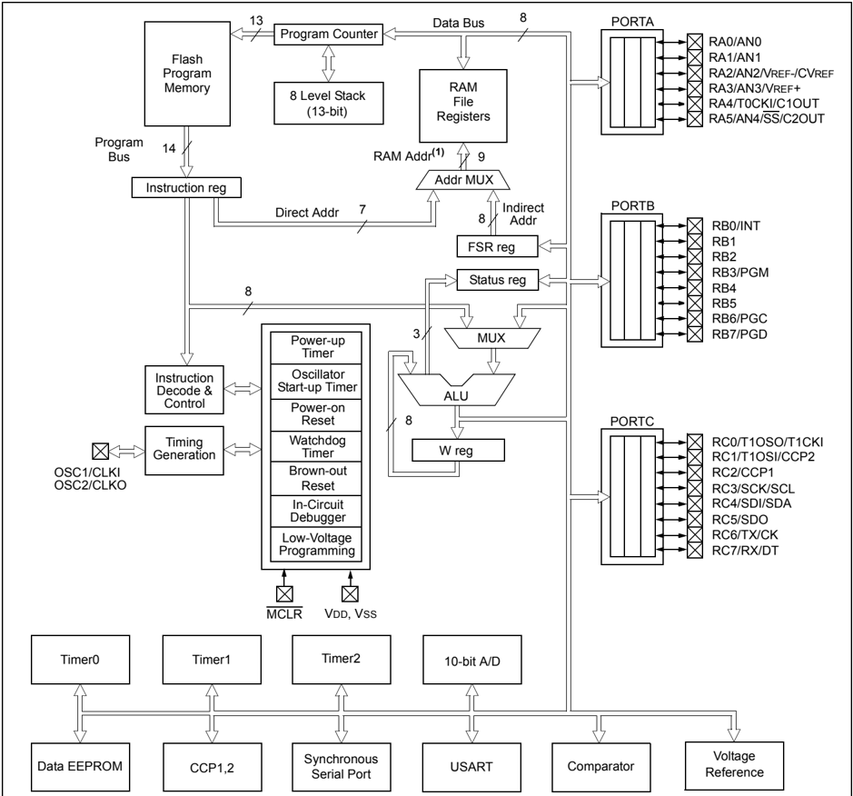
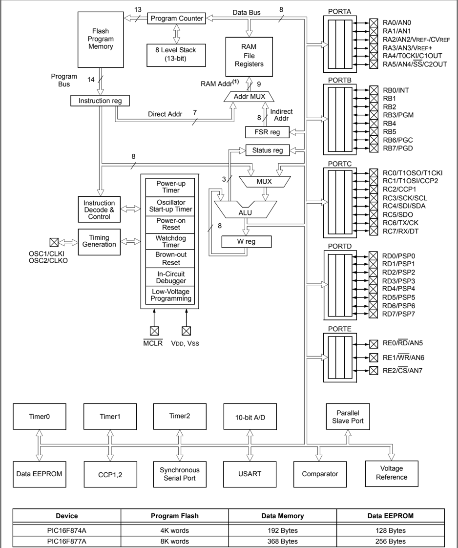
The available features are summarized in Table 1-1. Block diagrams of the PIC16F873A/876A and PIC16F874A/877A devices are provided in Figure 1-1 and Figure 1-2, respectively. The pinouts for these device families are listed in Table 1-2 and Table 1-3.
Additional information may be found in the PIC® Mid-Range Reference Manual (DS33023), which may be obtained from your local Microchip Sales Representative or downloaded from the Microchip web site. The Reference Manual should be considered a complementary document to this data sheet and is highly recommended reading for a better understanding of the device architecture and operation of the peripheral modules.
TABLE 1-1: PIC16F87XA DEVICE FEATURES
| Key Features | PIC16F873A | PIC16F874A | PIC16F876A | PIC16F877A |
|---|---|---|---|---|
| Operating Frequency | DC – 20 MHz | DC – 20 MHz | DC – 20 MHz | DC – 20 MHz |
| Resets (and Delays) | POR, BOR (PWRT, OST) | POR, BOR (PWRT, OST) | POR, BOR (PWRT, OST) | POR, BOR (PWRT, OST) |
| Flash Program Memory (14-bit words) | 4K | 4K | 8K | 8K |
| Data Memory (bytes) | 192 | 192 | 368 | 368 |
| EEPROM Data Memory (bytes) | 128 | 128 | 256 | 256 |
| Interrupts | 14 | 15 | 14 | 15 |
| I/O Ports | Ports A, B, C | Ports A, B, C, D, E | Ports A, B, C | Ports A, B, C, D, E |
| Timers | 3 | 3 | 3 | 3 |
| Capture/Compare/PWM modules | 2 | 2 | 2 | 2 |
| Serial Communications | MSSP, USART | MSSP, USART | MSSP, USART | MSSP, USART |
| Parallel Communications | — | PSP | — | PSP |
| 10-bit Analog-to-Digital Module | 5 input channels | 8 input channels | 5 input channels | 8 input channels |
| Analog Comparators | 2 | 2 | 2 | 2 |
| Instruction Set | 35 Instructions | 35 Instructions | 35 Instructions | 35 Instructions |
| Packages | 28-pin PDIP28-pin SOIC28-pin SSOP28-pin QFN | 40-pin PDIP44-pin PLCC44-pin TQFP44-pin QFN | 28-pin PDIP28-pin SOIC28-pin SSOP28-pin QFN | 40-pin PDIP44-pin PLCC44-pin TQFP44-pin QFN |
FIGURE 1-1: PIC16F873A/876A BLOCK DIAGRAM
| Device | Program Flash | Data Memory | Data EEPROM |
|---|---|---|---|
| PIC16F873A | 4K words | 192 Bytes | 128 Bytes |
| PIC16F876A | 8K words | 368 Bytes | 256 Bytes |
Note 1: Higher order bits are from the Status register.
FIGURE 1-2: PIC16F874A/877A BLOCK DIAGRAM
| Device | Program Flash | Data Memory | Data EEPROM |
|---|---|---|---|
| PIC16F874A | 4K words | 192 Bytes | 128 Bytes |
| PIC16F877A | 8K words | 368 Bytes | 256 Bytes |
Note 1: Higher order bits are from the Status register.
TABLE 1-2: PIC16F873A/876A PINOUT DESCRIPTION
Legend: I = input O = output I/O = input/output P = power — = Not used TTL = TTL input ST = Schmitt Trigger input
Note 1: This buffer is a Schmitt Trigger input when configured as the external interrupt. 2: This buffer is a Schmitt Trigger input when used in Serial Programming mode. 3: This buffer is a Schmitt Trigger input when configured in RC Oscillator mode and a CMOS input otherwise.
TABLE 1-2: PIC16F873A/876A PINOUT DESCRIPTION (CONTINUED)
| Pin Name | PDIP, SOIC, SSOP Pin# | QFN Pin# | I/O/P Type | Buffer Type | Description |
|---|---|---|---|---|---|
| RB0/INT | 21 | 18 | I/O | TTL/ST⁽¹⁾ | PORTB is a bidirectional I/O port. PORTB can be software programmed for internal weak pull-ups on all inputs. |
| RB0 | I | Digital I/O. | |||
| INT | External interrupt. | ||||
| RB1 | 22 | 19 | I/O | TTL | Digital I/O. |
| RB2 | 23 | 20 | I/O | TTL | Digital I/O. |
| RB3/PGM | 24 | 21 | I/O | TTL | Digital I/O. |
| RB3 | Low-voltage (single-supply) ICSP programming enable pin. | ||||
| PGM | I | ||||
| RB4 | 25 | 22 | I/O | TTL | Digital I/O. |
| RB5 | 26 | 23 | I/O | TTL | Digital I/O. |
| RB6/PGC | 27 | 24 | I/O | TTL/ST⁽²⁾ | Digital I/O. |
| RB6 | In-circuit debugger and ICSP programming clock. | ||||
| PGC | I | ||||
| RB7/PGD | 28 | 25 | I/O | TTL/ST⁽²⁾ | Digital I/O. |
| RB7 | In-circuit debugger and ICSP programming data. | ||||
| PGD | I/O | ||||
| RC0/T1OSO/T1CKI | 11 | 8 | I/O | ST | PORTC is a bidirectional I/O port. |
| RC0 | O | Digital I/O. | |||
| T1OSO | Timer1 oscillator output. | ||||
| T1CKI | I | Timer1 external clock input. | |||
| RC1/T1OSI/CCP2 | 12 | 9 | I/O | ST | Digital I/O. |
| RC1 | Timer1 oscillator input. | ||||
| T1OSI | I | ||||
| CCP2 | I/O | Capture2 input, Compare2 output, PWM2 output. | |||
| RC2/CCP1 | 13 | 10 | I/O | ST | Digital I/O. |
| RC2 | Capture1 input, Compare1 output, PWM1 output. | ||||
| CCP1 | I/O | ||||
| RC3/SCK/SCL | 14 | 11 | I/O | ST | Digital I/O. |
| RC3 | Synchronous serial clock input/output for SPI mode. | ||||
| SCK | I/O | Synchronous serial clock input/output for I²C mode. | |||
| SCL | I/O | ||||
| RC4/SDI/SDA | 15 | 12 | I/O | ST | Digital I/O. |
| RC4 | SPI data in. | ||||
| SDI | I | I²C data I/O. | |||
| SDA | I/O | ||||
| RC5/SDO | 16 | 13 | I/O | ST | Digital I/O. |
| RC5 | SPI data out. | ||||
| SDO | O | ||||
| RC6/TX/CK | 17 | 14 | I/O | ST | Digital I/O. |
| RC6 | USART asynchronous transmit. | ||||
| TX | O | USART1 synchronous clock. | |||
| CK | I/O | ||||
| RC7/RX/DT | 18 | 15 | I/O | ST | Digital I/O. |
| RC7 | USART asynchronous receive. | ||||
| RX | I | USART synchronous data. | |||
| DT | I/O | ||||
| VSS | 8, 19 | 5, 6 | P | — | Ground reference for logic and I/O pins. |
| VDD | 20 | 17 | P | — | Positive supply for logic and I/O pins. |
Legend: I = input O = output I/O = input/output P = power
— = Not used TTL = TTL input ST = Schmitt Trigger input
Note 1: This buffer is a Schmitt Trigger input when configured as the external interrupt.
2: This buffer is a Schmitt Trigger input when used in Serial Programming mode.
3: This buffer is a Schmitt Trigger input when configured in RC Oscillator mode and a CMOS input otherwise.
TABLE 1-3: PIC16F874A/877A PINOUT DESCRIPTION
| Pin Name | PDIP Pin# | PLCC Pin# | TQFP Pin# | QFN Pin# | I/O/P Type | Buffer Type | Description |
|---|---|---|---|---|---|---|---|
| OSC1/CLKIOSC1CLKI | 13 | 14 | 30 | 32 | II | ST/CMOS⁽⁴⁾ | Oscillator crystal or external clock input.Oscillator crystal input or external clock source input. ST buffer when configured in RC mode; otherwise CMOS.External clock source input. Always associated with pin function OSC1 (see OSC1/CLKI, OSC2/CLKO pins). |
| OSC2/CLKOOSC2CLKO | 14 | 15 | 31 | 33 | OO | — | Oscillator crystal or clock output.Oscillator crystal output.Connects to crystal or resonator in Crystal Oscillator mode.In RC mode, OSC2 pin outputs CLKO, which has 1/4 the frequency of OSC1 and denotes the instruction cycle rate. |
| MCLR/VPPMCLRVPP | 1 | 2 | 18 | 18 | IP | ST | Master Clear (input) or programming voltage (output).Master Clear (Reset) input. This pin is an active low Reset to the device.Programming voltage input. |
| RA0/AN0RA0AN0RA1/AN1RA1AN1RA2/AN2/VREF-/CVREFRA2AN2VREF-CVREFRA3/AN3/VREF+RA3AN3VREF+RA4/T0CKI/C1OUTRA4T0CKIC1OUTRA5/AN4/SS/C2OUTRA5AN4SSC2OUT | 234567 | 345678 | 192021222324 | 192021222324 | I/OII/OII/OIIOI/OIII/OIOI/OIIO | TTLTTLTTLTTLSTTTL | PORTA is a bidirectional I/O port.Digital I/O.Analog input 0.Digital I/O.Analog input 1.Digital I/O.Analog input 2.A/D reference voltage (Low) input.Comparator VREF output.Digital I/O.Analog input 3.A/D reference voltage (High) input.Digital I/O – Open-drain when configured as output.Timer0 external clock input.Comparator 1 output.Digital I/O.Analog input 4.SPI slave select input.Comparator 2 output. |
Legend: I = input O = output I/O = input/output P = power— = Not used TTL = TTL input ST = Schmitt Trigger input
Note 1: This buffer is a Schmitt Trigger input when configured as the external interrupt.2: This buffer is a Schmitt Trigger input when used in Serial Programming mode.3: This buffer is a Schmitt Trigger input when configured in RC Oscillator mode and a CMOS input otherwise.
DS39582C-page 10 © 2001-2013 Microchip Technology Inc.
TABLE 1-3: PIC16F874A/877A PINOUT DESCRIPTION (CONTINUED)
| Pin Name | PDIP Pin# | PLCC Pin# | TQFP Pin# | QFN Pin# | I/O/P Type | Buffer Type | Description |
|---|---|---|---|---|---|---|---|
| RB0/INTRB0INT | 33 | 36 | 8 | 9 | I/OI | TTL/ST(1) | PORTB is a bidirectional I/O port. PORTB can be software programmed for internal weak pull-up on all inputs.Digital I/O.External interrupt. |
| RB1 | 34 | 37 | 9 | 10 | I/O | TTL | Digital I/O. |
| RB2 | 35 | 38 | 10 | 11 | I/O | TTL | Digital I/O. |
| RB3/PGMRB3PGM | 36 | 39 | 11 | 12 | I/OI | TTL | Digital I/O.Low-voltage ICSP programming enable pin. |
| RB4 | 37 | 41 | 14 | 14 | I/O | TTL | Digital I/O. |
| RB5 | 38 | 42 | 15 | 15 | I/O | TTL | Digital I/O. |
| RB6/PGCRB6PGC | 39 | 43 | 16 | 16 | I/OI | TTL/ST(2) | Digital I/O.In-circuit debugger and ICSP programming clock. |
| RB7/PGDRB7PGD | 40 | 44 | 17 | 17 | I/OI/O | TTL/ST(2) | Digital I/O.In-circuit debugger and ICSP programming data. |
Legend:
I = input
O = output
I/O = input/output
P = power
— = Not used
TTL = TTL input
ST = Schmitt Trigger input
Note 1: This buffer is a Schmitt Trigger input when configured as the external interrupt.
Note 2: This buffer is a Schmitt Trigger input when used in Serial Programming mode.
Note 3: This buffer is a Schmitt Trigger input when configured in RC Oscillator mode and a CMOS input otherwise.
TABLE 1-3: PIC16F874A/877A PINOUT DESCRIPTION (CONTINUED)
| Pin Name | PDIP Pin# | PLCC Pin# | TQFP Pin# | QFN Pin# | I/O/P Type | Buffer Type | Description |
|---|---|---|---|---|---|---|---|
| RC0/T1OSO/T1CKIRC0T1OSOT1CKI | 15 | 16 | 32 | 34 | I/OOI | ST | PORTC is a bidirectional I/O port.Digital I/O.Timer1 oscillator output.Timer1 external clock input. |
| RC1/T1OSI/CCP2RC1T1OSICCP2 | 16 | 18 | 35 | 35 | I/OII/O | ST | Digital I/O.Timer1 oscillator input.Capture2 input, Compare2 output, PWM2 output. |
| RC2/CCP1RC2CCP1 | 17 | 19 | 36 | 36 | I/OI/O | ST | Digital I/O.Capture1 input, Compare1 output, PWM1 output. |
| RC3/SCK/SCLRC3SCKSCL | 18 | 20 | 37 | 37 | I/OI/OI/O | ST | Digital I/O.Synchronous serial clock input/output for SPI mode.Synchronous serial clock input/output for I²C mode. |
| RC4/SDI/SDARC4SDISDA | 23 | 25 | 42 | 42 | I/OII/O | ST | Digital I/O.SPI data in.I²C data I/O. |
| RC5/SDORC5SDO | 24 | 26 | 43 | 43 | I/OO | ST | Digital I/O.SPI data out. |
| RC6/TX/CKRC6TXCK | 25 | 27 | 44 | 44 | I/OOI/O | ST | Digital I/O.USART asynchronous transmit.USART1 synchronous clock. |
| RC7/RX/DTRC7RXDT | 26 | 29 | 1 | 1 | I/OII/O | ST | Digital I/O.USART asynchronous receive.USART synchronous data. |
Legend: I = input O = output I/O = input/output P = power— = Not used TTL = TTL input ST = Schmitt Trigger input
Note 1: This buffer is a Schmitt Trigger input when configured as the external interrupt.2: This buffer is a Schmitt Trigger input when used in Serial Programming mode.3: This buffer is a Schmitt Trigger input when configured in RC Oscillator mode and a CMOS input otherwise.
DS39582C-page 12 © 2001-2013 Microchip Technology Inc.
TABLE 1-3: PIC16F874A/877A PINOUT DESCRIPTION (CONTINUED)
| Pin Name | PDIP Pin# | PLCC Pin# | TQFP Pin# | QFN Pin# | I/O/P Type | Buffer Type | Description |
|---|---|---|---|---|---|---|---|
| RD0/PSP0RD0PSP0 | 19 | 21 | 38 | 38 | I/OI/O | ST/TTL⁽³⁾ | PORTD is a bidirectional I/O port or Parallel Slave Port when interfacing to a microprocessor bus.Digital I/O.Parallel Slave Port data. |
| RD1/PSP1RD1PSP1 | 20 | 22 | 39 | 39 | I/OI/O | ST/TTL⁽³⁾ | Digital I/O.Parallel Slave Port data. |
| RD2/PSP2RD2PSP2 | 21 | 23 | 40 | 40 | I/OI/O | ST/TTL⁽³⁾ | Digital I/O.Parallel Slave Port data. |
| RD3/PSP3RD3PSP3 | 22 | 24 | 41 | 41 | I/OI/O | ST/TTL⁽³⁾ | Digital I/O.Parallel Slave Port data. |
| RD4/PSP4RD4PSP4 | 27 | 30 | 2 | 2 | I/OI/O | ST/TTL⁽³⁾ | Digital I/O.Parallel Slave Port data. |
| RD5/PSP5RD5PSP5 | 28 | 31 | 3 | 3 | I/OI/O | ST/TTL⁽³⁾ | Digital I/O.Parallel Slave Port data. |
| RD6/PSP6RD6PSP6 | 29 | 32 | 4 | 4 | I/OI/O | ST/TTL⁽³⁾ | Digital I/O.Parallel Slave Port data. |
| RD7/PSP7RD7PSP7 | 30 | 33 | 5 | 5 | I/OI/O | ST/TTL⁽³⁾ | Digital I/O.Parallel Slave Port data. |
| RE0/RD/AN5RE0RDAN5 | 8 | 9 | 25 | 25 | I/OII | ST/TTL⁽³⁾ | PORTE is a bidirectional I/O port.Digital I/O.Read control for Parallel Slave Port.Analog input 5. |
| RE1/WR/AN6RE1WRAN6 | 9 | 10 | 26 | 26 | I/OII | ST/TTL⁽³⁾ | Digital I/O.Write control for Parallel Slave Port.Analog input 6. |
| RE2/CS/AN7RE2CSAN7 | 10 | 11 | 27 | 27 | I/OII | ST/TTL⁽³⁾ | Digital I/O.Chip select control for Parallel Slave Port.Analog input 7. |
| VSS | 12, 31 | 13, 34 | 6, 29 | 6, 30, 31 | P | — | Ground reference for logic and I/O pins. |
| VDD | 11, 32 | 12, 35 | 7, 28 | 7, 8, 28, 29 | P | — | Positive supply for logic and I/O pins. |
| NC | — | 1, 17, 28, 40 | 12,13, 33, 34 | 13 | — | — | These pins are not internally connected. These pins should be left unconnected. |
Legend: I = input O = output I/O = input/output P = power— = Not used TTL = TTL input ST = Schmitt Trigger input
Note 1: This buffer is a Schmitt Trigger input when configured as the external interrupt.2: This buffer is a Schmitt Trigger input when used in Serial Programming mode.3: This buffer is a Schmitt Trigger input when configured in RC Oscillator mode and a CMOS input otherwise.
NOTES:
DS39582C-page 14 © 2001-2013 Microchip Technology Inc.
2.0 MEMORY ORGANIZATION
There are three memory blocks in each of the PIC16F87XA devices. The program memory and data memory have separate buses so that concurrent access can occur and is detailed in this section. The EEPROM data memory block is detailed in Section 3.0 "Data EEPROM and Flash Program Memory".
Additional information on device memory may be found in the PIC® Mid-Range MCU Family Reference Manual (DS33023).
2.1 Program Memory Organization
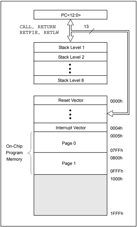
The PIC16F87XA devices have a 13-bit program counter capable of addressing an 8K word x 14 bit program memory space. The PIC16F876A/877A devices have 8K words x 14 bits of Flash program memory, while PIC16F873A/874A devices have 4K words x 14 bits. Accessing a location above the physically implemented address will cause a wraparound.
The Reset vector is at 0000h and the interrupt vector is at 0004h.
FIGURE 2-1: PIC16F876A/877A PROGRAM MEMORY MAP AND STACK
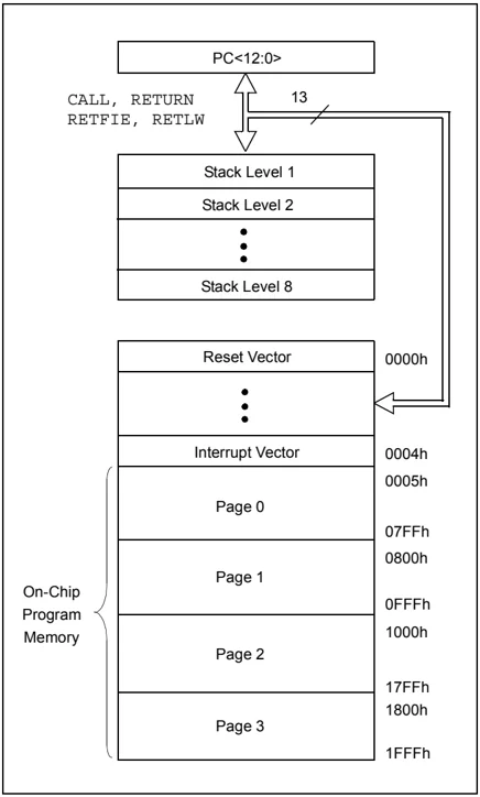
FIGURE 2-2: PIC16F873A/874A PROGRAM MEMORY MAP AND STACK
2.2 Data Memory Organization
The data memory is partitioned into multiple banks which contain the General Purpose Registers and the Special Function Registers. Bits RP1 (Status<6>) and RP0 (Status<5>) are the bank select bits.
Each bank extends up to 7Fh (128 bytes). The lower locations of each bank are reserved for the Special Function Registers. Above the Special Function Registers are General Purpose Registers, implemented as static RAM. All implemented banks contain Special Function Registers. Some frequently used Special Function Registers from one bank may be mirrored in another bank for code reduction and quicker access.
Note: The EEPROM data memory description can be found in Section 3.0 “Data EEPROM and Flash Program Memory” of this data sheet.
2.2.1 GENERAL PURPOSE REGISTER FILE
The register file can be accessed either directly, or indirectly, through the File Select Register (FSR).
FIGURE 2-3: PIC16F876A/877A REGISTER FILE MAP
| File Address | File Address | File Address | File Address | ||||
|---|---|---|---|---|---|---|---|
| Indirect addr.(*) | 00h | Indirect addr.(*) | 80h | Indirect addr.(*) | 100h | Indirect addr.(*) | 180h |
| TMR0 | 01h | OPTION_REG | 81h | TMR0 | 101h | OPTION_REG | 181h |
| PCL | 02h | PCL | 82h | PCL | 102h | PCL | 182h |
| STATUS | 03h | STATUS | 83h | STATUS | 103h | STATUS | 183h |
| FSR | 04h | FSR | 84h | FSR | 104h | FSR | 184h |
| PORTA | 05h | TRISA | 85h | 105h | 185h | ||
| PORTB | 06h | TRISB | 86h | PORTB | 106h | TRISB | 186h |
| PORTC | 07h | TRISC | 87h | 107h | 187h | ||
| PORTD(1) | 08h | TRISD(1) | 88h | 108h | 188h | ||
| PORTE(1) | 09h | TRISE(1) | 89h | 109h | 189h | ||
| PCLATH | 0Ah | PCLATH | 8Ah | PCLATH | 10Ah | PCLATH | 18Ah |
| INTCON | 0Bh | INTCON | 8Bh | INTCON | 10Bh | INTCON | 18Bh |
| PIR1 | 0Ch | PIE1 | 8Ch | EEDATA | 10Ch | EECON1 | 18Ch |
| PIR2 | 0Dh | PIE2 | 8Dh | EEADR | 10Dh | EECON2 | 18Dh |
| TMR1L | 0Eh | PCON | 8Eh | EEDATH | 10Eh | Reserved(2) | 18Eh |
| TMR1H | 0Fh | 8Fh | EEADRH | 10Fh | Reserved(2) | 18Fh | |
| T1CON | 10h | 90h | 110h | 190h | |||
| TMR2 | 11h | SSPCON2 | 91h | 111h | 191h | ||
| T2CON | 12h | PR2 | 92h | 112h | 192h | ||
| SSPBUF | 13h | SSPADD | 93h | 113h | 193h | ||
| SSPCON | 14h | SSPSTAT | 94h | 114h | 194h | ||
| CCPR1L | 15h | 95h | 115h | 195h | |||
| CCPR1H | 16h | 96h | 116h | 196h | |||
| CCP1CON | 17h | 97h | General Purpose Register 16 Bytes | 117h | General Purpose Register 16 Bytes | 197h | |
| RCSTA | 18h | TXSTA | 98h | 118h | 198h | ||
| TXREG | 19h | SPBRG | 99h | 119h | 199h | ||
| RCREG | 1Ah | 9Ah | 11Ah | 19Ah | |||
| CCPR2L | 1Bh | 9Bh | 11Bh | 19Bh | |||
| CCPR2H | 1Ch | CMCON | 9Ch | 11Ch | 19Ch | ||
| CCP2CON | 1Dh | CVRCON | 9Dh | 11Dh | 19Dh | ||
| ADRESH | 1Eh | ADRESL | 9Eh | 11Eh | 19Eh | ||
| ADCON0 | 1Fh | ADCON1 | 9Fh | 11Fh | 19Fh | ||
| 20h | A0h | 120h | 1A0h | ||||
| General Purpose Register 96 Bytes | 7Fh | General Purpose Register 80 Bytes | FFh | General Purpose Register 80 Bytes | 17Fh | General Purpose Register 80 Bytes | 1FFh |
| accesses 70h-7Fh | accesses 70h-7Fh | accesses 70h - 7Fh | |||||
| Bank 0 | Bank 1 | Bank 2 | Bank 3 |
- Unimplemented data memory locations, read as ‘0’.
-
- Not a physical register.
- Note 1: These registers are not implemented on the PIC16F876A.
- Note 2: These registers are reserved; maintain these registers clear.
FIGURE 2-4: PIC16F873A/874A REGISTER FILE MAP
| File Address | File Address | File Address | File Address |
|---|---|---|---|
| Indirect addr.(*) 00h | Indirect addr.(*) 80h | Indirect addr.(*) 100h | Indirect addr.(*) 180h |
| TMR0 01h | OPTION_REG 81h | TMR0 101h | OPTION_REG 181h |
| PCL 02h | PCL 82h | PCL 102h | PCL 182h |
| STATUS 03h | STATUS 83h | STATUS 103h | STATUS 183h |
| FSR 04h | FSR 84h | FSR 104h | FSR 184h |
| PORTA 05h | TRISA 85h | 105h | 185h |
| PORTB 06h | TRISB 86h | PORTB 106h | TRISB 186h |
| PORTC 07h | TRISC 87h | 107h | 187h |
| PORTD(1) 08h | TRISD(1) 88h | 108h | 188h |
| PORTE(1) 09h | TRISE(1) 89h | 109h | 189h |
| PCLATH 0Ah | PCLATH 8Ah | PCLATH 10Ah | PCLATH 18Ah |
| INTCON 0Bh | INTCON 8Bh | INTCON 10Bh | INTCON 18Bh |
| PIR1 0Ch | PIE1 8Ch | EEDATA 10Ch | EECON1 18Ch |
| PIR2 0Dh | PIE2 8Dh | EEADR 10Dh | EECON2 18Dh |
| TMR1L 0Eh | PCON 8Eh | EEDATH 10Eh | Reserved(2) 18Eh |
| TMR1H 0Fh | 8Fh | EEADRH 10Fh | Reserved(2) 18Fh |
| T1CON 10h | 90h | 110h | 190h |
| TMR2 11h | SSPCON2 91h | ||
| T2CON 12h | PR2 92h | ||
| SSPBUF 13h | SSPADD 93h | ||
| SSPCON 14h | SSPSTAT 94h | ||
| CCPR1L 15h | 95h | ||
| CCPR1H 16h | 96h | ||
| CCP1CON 17h | 97h | ||
| RCSTA 18h | TXSTA 98h | ||
| TXREG 19h | SPBRG 99h | ||
| RCREG 1Ah | 9Ah | ||
| CCPR2L 1Bh | 9Bh | ||
| CCPR2H 1Ch | CMCON 9Ch | ||
| CCP2CON 1Dh | CVRCON 9Dh | ||
| ADRESH 1Eh | ADRESL 9Eh | ||
| ADCON0 1Fh | ADCON1 9Fh | ||
| 20h | A0h | 120h | 1A0h |
| General Purpose Register 96 Bytes | General Purpose Register 96 Bytes | accesses 20h-7Fh | accesses A0h - FFh |
| 7Fh | FFh | 16Fh 170h | 1EFh 1F0h |
| Bank 0 | Bank 1 | Bank 2 | Bank 3 |
| 17Fh | 1FFh |
- Unimplemented data memory locations, read as ‘0’.
-
- Not a physical register.
- Note 1: These registers are not implemented on the PIC16F873A.
- Note 2: These registers are reserved; maintain these registers clear.
DS39582C-page 18 © 2001-2013 Microchip Technology Inc.
2.2.2 SPECIAL FUNCTION REGISTERS
The Special Function Registers are registers used by the CPU and peripheral modules for controlling the desired operation of the device. These registers are implemented as static RAM. A list of these registers is given in Table 2-1.
The Special Function Registers can be classified into two sets: core (CPU) and peripheral. Those registers associated with the core functions are described in detail in this section. Those related to the operation of the peripheral features are described in detail in the peripheral features section.
TABLE 2-1: SPECIAL FUNCTION REGISTER SUMMARY
| Address | Name | Bit 7 | Bit 6 | Bit 5 | Bit 4 | Bit 3 | Bit 2 | Bit 1 | Bit 0 | Value on: POR, BOR | Details on page: |
|---|---|---|---|---|---|---|---|---|---|---|---|
| Bank 0 | |||||||||||
| 00h⁽³⁾ | INDF | Addressing this location uses contents of FSR to address data memory (not a physical register) | 0000 0000 | 31, 150 | |||||||
| 01h | TMR0 | Timer0 Module Register | xxxx xxxx | 55, 150 | |||||||
| 02h⁽³⁾ | PCL | Program Counter (PC) Least Significant Byte | 0000 0000 | 30, 150 | |||||||
| 03h⁽³⁾ | STATUS | IRP | RP1 | RP0 | TO | PD | Z | DC | C | 0001 1xxx | 22, 150 |
| 04h⁽³⁾ | FSR | Indirect Data Memory Address Pointer | xxxx xxxx | 31, 150 | |||||||
| 05h | PORTA | — | — | PORTA Data Latch when written: PORTA pins when read | --0x 0000 | 43, 150 | |||||
| 06h | PORTB | PORTB Data Latch when written: PORTB pins when read | xxxx xxxx | 45, 150 | |||||||
| 07h | PORTC | PORTC Data Latch when written: PORTC pins when read | xxxx xxxx | 47, 150 | |||||||
| 08h⁽⁴⁾ | PORTD | PORTD Data Latch when written: PORTD pins when read | xxxx xxxx | 48, 150 | |||||||
| 09h⁽⁴⁾ | PORTE | — | — | — | — | — | RE2 | RE1 | RE0 | ---- -xxx | 49, 150 |
| 0Ah⁽¹,³⁾ | PCLATH | — | — | — | Write Buffer for the upper 5 bits of the Program Counter | ---0 0000 | 30, 150 | ||||
| 0Bh⁽³⁾ | INTCON | GIE | PEIE | TMR0IE | INTE | RBIE | TMR0IF | INTF | RBIF | 0000 000x | 24, 150 |
| 0Ch | PIR1 | PSPIF⁽³⁾ | ADIF | RCIF | TXIF | SSPIF | CCP1IF | TMR2IF | TMR1IF | 0000 0000 | 26, 150 |
| 0Dh | PIR2 | — | CMIF | — | EEIF | BCLIF | — | — | CCP2IF | -0-0 0--0 | 28, 150 |
| 0Eh | TMR1L | Holding Register for the Least Significant Byte of the 16-bit TMR1 Register | xxxx xxxx | 60, 150 | |||||||
| 0Fh | TMR1H | Holding Register for the Most Significant Byte of the 16-bit TMR1 Register | xxxx xxxx | 60, 150 | |||||||
| 10h | T1CON | — | — | T1CKPS1 | T1CKPS0 | T1OSCEN | T1SYNC | TMR1CS | TMR1ON | --00 0000 | 57, 150 |
| 11h | TMR2 | Timer2 Module Register | 0000 0000 | 62, 150 | |||||||
| 12h | T2CON | — | TOUTPS3 | TOUTPS2 | TOUTPS1 | TOUTPS0 | TMR2ON | T2CKPS1 | T2CKPS0 | -000 0000 | 61, 150 |
| 13h | SSPBUF | Synchronous Serial Port Receive Buffer/Transmit Register | xxxx xxxx | 79, 150 | |||||||
| 14h | SSPCON | WCOL | SSPOV | SSPEN | CKP | SSPM3 | SSPM2 | SSPM1 | SSPM0 | 0000 0000 | 82, 82, 150 |
| 15h | CCPR1L | Capture/Compare/PWM Register 1 (LSB) | xxxx xxxx | 63, 150 | |||||||
| 16h | CCPR1H | Capture/Compare/PWM Register 1 (MSB) | xxxx xxxx | 63, 150 | |||||||
| 17h | CCP1CON | — | — | CCP1X | CCP1Y | CCP1M3 | CCP1M2 | CCP1M1 | CCP1M0 | --00 0000 | 64, 150 |
| 18h | RCSTA | SPEN | RX9 | SREN | CREN | ADDEN | FERR | OERR | RX9D | 0000 000x | 112, 150 |
| 19h | TXREG | USART Transmit Data Register | 0000 0000 | 118, 150 | |||||||
| 1Ah | RCREG | USART Receive Data Register | 0000 0000 | 118, 150 | |||||||
| 1Bh | CCPR2L | Capture/Compare/PWM Register 2 (LSB) | xxxx xxxx | 63, 150 | |||||||
| 1Ch | CCPR2H | Capture/Compare/PWM Register 2 (MSB) | xxxx xxxx | 63, 150 | |||||||
| 1Dh | CCP2CON | — | — | CCP2X | CCP2Y | CCP2M3 | CCP2M2 | CCP2M1 | CCP2M0 | --00 0000 | 64, 150 |
| 1Eh | ADRESH | A/D Result Register High Byte | xxxx xxxx | 133, 150 | |||||||
| 1Fh | ADCON0 | ADCS1 | ADCS0 | CHS2 | CHS1 | CHS0 | GO/DONE | — | ADON | 0000 00-0 | 127, 150 |
Legend: x = unknown, u = unchanged, q = value depends on condition, - = unimplemented, read as ‘0’, r = reserved.
Shaded locations are unimplemented, read as ‘0’.
Note 1: The upper byte of the program counter is not directly accessible. PCLATH is a holding register for the PC<12:8>, whose contents are transferred to the upper byte of the program counter.
2: Bits PSPIE and PSPIF are reserved on PIC16F873A/876A devices; always maintain these bits clear.
3: These registers can be addressed from any bank.
4: PORTD, PORTE, TRISD and TRISE are not implemented on PIC16F873A/876A devices, read as ‘0’.
5: Bit 4 of EEADRH implemented only on the PIC16F876A/877A devices.
TABLE 2-1: SPECIAL FUNCTION REGISTER SUMMARY (CONTINUED)
| Address | Name | Bit 7 | Bit 6 | Bit 5 | Bit 4 | Bit 3 | Bit 2 | Bit 1 | Bit 0 | Value on: POR, BOR | Details on page: |
|---|---|---|---|---|---|---|---|---|---|---|---|
| Bank 1 | |||||||||||
| 80h⁽³⁾ | INDF | Addressing this location uses contents of FSR to address data memory (not a physical register) | 0000 0000 | 31, 150 | |||||||
| 81h | OPTION_REG | RBPU | INTEDG | T0CS | T0SE | PSA | PS2 | PS1 | PS0 | 1111 1111 | 23, 150 |
| 82h⁽³⁾ | PCL | Program Counter (PC) Least Significant Byte | 0000 0000 | 30, 150 | |||||||
| 83h⁽³⁾ | STATUS | IRP | RP1 | RP0 | TO | PD | Z | DC | C | 0001 1xxx | 22, 150 |
| 84h⁽³⁾ | FSR | Indirect Data Memory Address Pointer | xxxx xxxx | 31, 150 | |||||||
| 85h | TRISA | — | — | PORTA Data Direction Register | --11 1111 | 43, 150 | |||||
| 86h | TRISB | PORTB Data Direction Register | 1111 1111 | 45, 150 | |||||||
| 87h | TRISC | PORTC Data Direction Register | 1111 1111 | 47, 150 | |||||||
| 88h⁽⁴⁾ | TRISD | PORTD Data Direction Register | 1111 1111 | 48, 151 | |||||||
| 89h⁽⁴⁾ | TRISE | IBF | OBF | IBOV | PSPMODE | — | PORTE Data Direction bits | 0000 -111 | 50, 151 | ||
| 8Ah⁽¹,³⁾ | PCLATH | — | — | — | Write Buffer for the upper 5 bits of the Program Counter | ---0 0000 | 30, 150 | ||||
| 8Bh⁽³⁾ | INTCON | GIE | PEIE | TMR0IE | INTE | RBIE | TMR0IF | INTF | RBIF | 0000 000x | 24, 150 |
| 8Ch | PIE1 | PSPIE⁽²⁾ | ADIE | RCIE | TXIE | SSPIE | CCP1IE | TMR2IE | TMR1IE | 0000 0000 | 25, 151 |
| 8Dh | PIE2 | — | CMIE | — | EEIE | BCLIE | — | — | CCP2IE | -0-0 0--0 | 27, 151 |
| 8Eh | PCON | — | — | — | — | — | — | POR | BOR | 29, 151 | |
| 8Fh | — | Unimplemented | — | — | |||||||
| 90h | — | Unimplemented | — | — | |||||||
| 91h | SSPCON2 | GCEN | ACKSTAT | ACKDT | ACKEN | RCEN | PEN | RSEN | SEN | 0000 0000 | 83, 151 |
| 92h | PR2 | Timer2 Period Register | 1111 1111 | 62, 151 | |||||||
| 93h | SSPADD | Synchronous Serial Port (I²C mode) Address Register | 0000 0000 | 79, 151 | |||||||
| 94h | SSPSTAT | SMP | CKE | D/A | P | S | R/W | UA | BF | 0000 0000 | 79, 151 |
| 95h | — | Unimplemented | — | — | |||||||
| 96h | — | Unimplemented | — | — | |||||||
| 97h | — | Unimplemented | — | — | |||||||
| 98h | TXSTA | CSRC | TX9 | TXEN | SYNC | — | BRGH | TRMT | TX9D | 0000 -010 | 111, 151 |
| 99h | SPBRG | Baud Rate Generator Register | 0000 0000 | 113, 151 | |||||||
| 9Ah | — | Unimplemented | — | — | |||||||
| 9Bh | — | Unimplemented | — | — | |||||||
| 9Ch | CMCON | C2OUT | C1OUT | C2INV | C1INV | CIS | CM2 | CM1 | CM0 | 0000 0111 | 135, 151 |
| 9Dh | CVRCON | CVREN | CVROE | CVRR | — | CVR3 | CVR2 | CVR1 | CVR0 | 000- 0000 | 141, 151 |
| 9Eh | ADRESL | A/D Result Register Low Byte | xxxx xxxx | 133, 151 | |||||||
| 9Fh | ADCON1 | ADFM | ADCS2 | — | — | PCFG3 | PCFG2 | PCFG1 | PCFG0 | 00-- 0000 | 128, 151 |
Legend: x = unknown, u = unchanged, q = value depends on condition, - = unimplemented, read as ‘0’, r = reserved.
Shaded locations are unimplemented, read as ‘0’.
Note 1: The upper byte of the program counter is not directly accessible. PCLATH is a holding register for the PC<12:8>, whose contents are transferred to the upper byte of the program counter.
2: Bits PSPIE and PSPIF are reserved on PIC16F873A/876A devices; always maintain these bits clear.
3: These registers can be addressed from any bank.
4: PORTD, PORTE, TRISD and TRISE are not implemented on PIC16F873A/876A devices, read as ‘0’.
5: Bit 4 of EEADRH implemented only on the PIC16F876A/877A devices.
TABLE 2-1: SPECIAL FUNCTION REGISTER SUMMARY (CONTINUED)
| Address | Name | Bit 7 | Bit 6 | Bit 5 | Bit 4 | Bit 3 | Bit 2 | Bit 1 | Bit 0 | Value on: POR, BOR | Details on page: |
|---|---|---|---|---|---|---|---|---|---|---|---|
| Bank 2 | |||||||||||
| 100h⁽³⁾ | INDF | Addressing this location uses contents of FSR to address data memory (not a physical register) | 0000 0000 | 31, 150 | |||||||
| 101h | TMR0 | Timer0 Module Register | xxxx xxxx | 55, 150 | |||||||
| 102h⁽³⁾ | PCL | Program Counter’s (PC) Least Significant Byte | 0000 0000 | 30, 150 | |||||||
| 103h⁽³⁾ | STATUS | IRP | RP1 | RP0 | TO | PD | Z | DC | C | 0001 1xxx | 22, 150 |
| 104h⁽³⁾ | FSR | Indirect Data Memory Address Pointer | xxxx xxxx | 31, 150 | |||||||
| 105h | — | Unimplemented | — | — | |||||||
| 106h | PORTB | PORTB Data Latch when written: PORTB pins when read | xxxx xxxx | 45, 150 | |||||||
| 107h | — | Unimplemented | — | — | |||||||
| 108h | — | Unimplemented | — | — | |||||||
| 109h | — | Unimplemented | — | — | |||||||
| 10Ah⁽¹,³⁾ | PCLATH | — | — | — | Write Buffer for the upper 5 bits of the Program Counter | ---0 0000 | 30, 150 | ||||
| 10Bh⁽³⁾ | INTCON | GIE | PEIE | TMR0IE | INTE | RBIE | TMR0IF | INTF | RBIF | 0000 000x | 24, 150 |
| 10Ch | EEDATA | EEPROM Data Register Low Byte | xxxx xxxx | 39, 151 | |||||||
| 10Dh | EEADR | EEPROM Address Register Low Byte | xxxx xxxx | 39, 151 | |||||||
| 10Eh | EEDATH | — | — | EEPROM Data Register High Byte | --xx xxxx | 39, 151 | |||||
| 10Fh | EEADRH | — | — | — | —⁽⁵⁾ | EEPROM Address Register High Byte | ---- xxxx | 39, 151 | |||
| Bank 3 | |||||||||||
| 180h⁽³⁾ | INDF | Addressing this location uses contents of FSR to address data memory (not a physical register) | 0000 0000 | 31, 150 | |||||||
| 181h | OPTION_REG | RBPU | INTEDG | T0CS | T0SE | PSA | PS2 | PS1 | PS0 | 1111 1111 | 23, 150 |
| 182h⁽³⁾ | PCL | Program Counter (PC) Least Significant Byte | 0000 0000 | 30, 150 | |||||||
| 183h⁽³⁾ | STATUS | IRP | RP1 | RP0 | TO | PD | Z | DC | C | 0001 1xxx | 22, 150 |
| 184h⁽³⁾ | FSR | Indirect Data Memory Address Pointer | xxxx xxxx | 31, 150 | |||||||
| 185h | — | Unimplemented | — | — | |||||||
| 186h | TRISB | PORTB Data Direction Register | 1111 1111 | 45, 150 | |||||||
| 187h | — | Unimplemented | — | — | |||||||
| 188h | — | Unimplemented | — | — | |||||||
| 189h | — | Unimplemented | — | — | |||||||
| 18Ah⁽¹,³⁾ | PCLATH | — | — | — | Write Buffer for the upper 5 bits of the Program Counter | ---0 0000 | 30, 150 | ||||
| 18Bh⁽³⁾ | INTCON | GIE | PEIE | TMR0IE | INTE | RBIE | TMR0IF | INTF | RBIF | 0000 000x | 24, 150 |
| 18Ch | EECON1 | EEPGD | — | — | — | WRERR | WREN | WR | RD | x--- x000 | 34, 151 |
| 18Dh | EECON2 | EEPROM Control Register 2 (not a physical register) | ---- ---- | 39, 151 | |||||||
| 18Eh | — | Reserved; maintain clear | 0000 0000 | — | |||||||
| 18Fh | — | Reserved; maintain clear | 0000 0000 | — |
Legend: x = unknown, u = unchanged, q = value depends on condition, - = unimplemented, read as ‘0’, r = reserved.
Shaded locations are unimplemented, read as ‘0’.
Note 1: The upper byte of the program counter is not directly accessible. PCLATH is a holding register for the PC<12:8>, whose contents are transferred to the upper byte of the program counter.
2: Bits PSPIE and PSPIF are reserved on PIC16F873A/876A devices; always maintain these bits clear.
3: These registers can be addressed from any bank.
4: PORTD, PORTE, TRISD and TRISE are not implemented on PIC16F873A/876A devices, read as ‘0’.
5: Bit 4 of EEADRH implemented only on the PIC16F876A/877A devices.
2.2.2.1 Status Register
The Status register contains the arithmetic status of the ALU, the Reset status and the bank select bits for data memory.
The Status register can be the destination for any instruction, as with any other register. If the Status register is the destination for an instruction that affects the Z, DC or C bits, then the write to these three bits is disabled. These bits are set or cleared according to the device logic. Furthermore, the \overlineTO and \overlinePD bits are not writable, therefore, the result of an instruction with the Status register as destination may be different than intended.
For example, CLRF STATUS, will clear the upper three bits and set the Z bit. This leaves the Status register as 000u u1uu (where u = unchanged).
It is recommended, therefore, that only BCF, BSF, SWAPF and MOVWF instructions are used to alter the Status register because these instructions do not affect the Z, C or DC bits from the Status register. For other instructions not affecting any status bits, see Section 15.0 "Instruction Set Summary".
Note: The C and DC bits operate as a borrow and digit borrow bit, respectively, in subtraction. See the SUBLW and SUBWF instructions for examples.
REGISTER 2-1: STATUS REGISTER (ADDRESS 03h, 83h, 103h, 183h)
\begin{tabular}{lllllllll} R/W-0 & R/W-0 & R/W-0 & R-1 & R-1 & R/W-x & R/W-x & R/W-x \ IRP & RP1 & RP0 & \overlineTO & \overlinePD & Z & DC & C \ bit 7 & & & & & & & bit 0 \ \end{tabular}
bit 7 IRP: Register Bank Select bit (used for indirect addressing) 1 = Bank 2, 3 (100h-1FFh) 0 = Bank 0, 1 (00h-FFh)
bit 6-5 RP1:RP0: Register Bank Select bits (used for direct addressing) 11 = Bank 3 (180h-1FFh) 10 = Bank 2 (100h-17Fh) 01 = Bank 1 (80h-FFh) 00 = Bank 0 (00h-7Fh) Each bank is 128 bytes.
bit 4 \overlineTO: Time-out bit 1 = After power-up, CLRWDT instruction or SLEEP instruction 0 = A WDT time-out occurred
bit 3 \overlinePD: Power-down bit 1 = After power-up or by the CLRWDT instruction 0 = By execution of the SLEEP instruction
bit 2 Z: Zero bit 1 = The result of an arithmetic or logic operation is zero 0 = The result of an arithmetic or logic operation is not zero
bit 1 DC: Digit carry/borrow bit (ADDWF, ADDLW, SUBLW, SUBWF instructions) (for borrow, the polarity is reversed) 1 = A carry-out from the 4th low order bit of the result occurred 0 = No carry-out from the 4th low order bit of the result
bit 0 C: Carry/borrow bit (ADDWF, ADDLW, SUBLW, SUBWF instructions) 1 = A carry-out from the Most Significant bit of the result occurred 0 = No carry-out from the Most Significant bit of the result occurred
Note: For borrow, the polarity is reversed. A subtraction is executed by adding the two's complement of the second operand. For rotate (RRF, RLF) instructions, this bit is loaded with either the high, or low order bit of the source register.
Legend: R = Readable bit W = Writable bit U = Unimplemented bit, read as '0'
- n = Value at POR '1' = Bit is set '0' = Bit is cleared x = Bit is unknown
2.2.2.2 OPTION_REG Register
The OPTION_REG Register is a readable and writable register, which contains various control bits to configure the TMR0 prescaler/WDT postscaler (single assignable register known also as the prescaler), the external INT interrupt, TMR0 and the weak pull-ups on PORTB.
Note: To achieve a 1:1 prescaler assignment for the TMR0 register, assign the prescaler to the Watchdog Timer.
REGISTER 2-2: OPTION_REG REGISTER (ADDRESS 81h, 181h)
bit 7 RBPU: PORTB Pull-up Enable bit 1 = PORTB pull-ups are disabled 0 = PORTB pull-ups are enabled by individual port latch values
bit 6 INTDG: Interrupt Edge Select bit 1 = Interrupt on rising edge of RB0/INT pin 0 = Interrupt on falling edge of RB0/INT pin
bit 5 T0CS: TMR0 Clock Source Select bit 1 = Transition on RA4/T0CKI pin 0 = Internal instruction cycle clock (CLKO)
bit 4 T0SE: TMR0 Source Edge Select bit 1 = Increment on high-to-low transition on RA4/T0CKI pin 0 = Increment on low-to-high transition on RA4/T0CKI pin
bit 3 PSA: Prescaler Assignment bit 1 = Prescaler is assigned to the WDT 0 = Prescaler is assigned to the Timer0 module
bit 2-0 PS2:PS0: Prescaler Rate Select bits
2.2.2.3 INTCON Register
The INTCON register is a readable and writable register, which contains various enable and flag bits for the TMR0 register overflow, RB port change and external RB0/INT pin interrupts.
Note: Interrupt flag bits are set when an interrupt condition occurs regardless of the state of its corresponding enable bit or the global enable bit, GIE (INTCON<7>). User software should ensure the appropriate interrupt flag bits are clear prior to enabling an interrupt.
REGISTER 2-3: INTCON REGISTER (ADDRESS 0Bh, 8Bh, 10Bh, 18Bh)
bit 7 bit 0
bit 7 GIE: Global Interrupt Enable bit 1 = Enables all unmasked interrupts 0 = Disables all interrupts
bit 6 PEIE: Peripheral Interrupt Enable bit 1 = Enables all unmasked peripheral interrupts 0 = Disables all peripheral interrupts
bit 5 TMR0IE: TMR0 Overflow Interrupt Enable bit 1 = Enables the TMR0 interrupt 0 = Disables the TMR0 interrupt
bit 4 INTE: RB0/INT External Interrupt Enable bit 1 = Enables the RB0/INT external interrupt 0 = Disables the RB0/INT external interrupt
bit 3 RBIE: RB Port Change Interrupt Enable bit 1 = Enables the RB port change interrupt 0 = Disables the RB port change interrupt
bit 2 TMR0IF: TMR0 Overflow Interrupt Flag bit 1 = TMR0 register has overflowed (must be cleared in software) 0 = TMR0 register did not overflow
bit 1 INTF: RB0/INT External Interrupt Flag bit 1 = The RB0/INT external interrupt occurred (must be cleared in software) 0 = The RB0/INT external interrupt did not occur
bit 0 RBIF: RB Port Change Interrupt Flag bit 1 = At least one of the RB7:RB4 pins changed state; a mismatch condition will continue to set the bit. Reading PORTB will end the mismatch condition and allow the bit to be cleared (must be cleared in software). 0 = None of the RB7:RB4 pins have changed state
Legend: R = Readable bit W = Writable bit U = Unimplemented bit, read as '0'
- n = Value at POR '1' = Bit is set '0' = Bit is cleared x = Bit is unknown
DS39582C-page 24 © 2001-2013 Microchip Technology Inc.
2.2.2.4 PIE1 Register
The PIE1 register contains the individual enable bits for the peripheral interrupts.
Note: Bit PEIE (INTCON<6>) must be set to enable any peripheral interrupt.
REGISTER 2-4: PIE1 REGISTER (ADDRESS 8Ch)
| R/W-0 | R/W-0 | R/W-0 | R/W-0 | R/W-0 | R/W-0 | R/W-0 | R/W-0 |
|---|---|---|---|---|---|---|---|
| PSPIE⁽¹⁾ | ADIE | RCIE | TXIE | SSPIE | CCP1IE | TMR2IE | TMR1IE |
| bit 7 | bit 0 |
bit 7
PSPIE: Parallel Slave Port Read/Write Interrupt Enable bit⁽¹⁾
1 = Enables the PSP read/write interrupt
0 = Disables the PSP read/write interrupt
Note 1: PSPIE is reserved on PIC16F873A/876A devices; always maintain this bit clear.
bit 6
ADIE: A/D Converter Interrupt Enable bit
1 = Enables the A/D converter interrupt
0 = Disables the A/D converter interrupt
bit 5
RCIE: USART Receive Interrupt Enable bit
1 = Enables the USART receive interrupt
0 = Disables the USART receive interrupt
bit 4
TXIE: USART Transmit Interrupt Enable bit
1 = Enables the USART transmit interrupt
0 = Disables the USART transmit interrupt
bit 3
SSPIE: Synchronous Serial Port Interrupt Enable bit
1 = Enables the SSP interrupt
0 = Disables the SSP interrupt
bit 2
CCP1IE: CCP1 Interrupt Enable bit
1 = Enables the CCP1 interrupt
0 = Disables the CCP1 interrupt
bit 1
TMR2IE: TMR2 to PR2 Match Interrupt Enable bit
1 = Enables the TMR2 to PR2 match interrupt
0 = Disables the TMR2 to PR2 match interrupt
bit 0
TMR1IE: TMR1 Overflow Interrupt Enable bit
1 = Enables the TMR1 overflow interrupt
0 = Disables the TMR1 overflow interrupt
Legend:
R = Readable bit
W = Writable bit
U = Unimplemented bit, read as ‘0’
- n = Value at POR
‘1’ = Bit is set
‘0’ = Bit is cleared
x = Bit is unknown
2.2.2.5 PIR1 Register
The PIR1 register contains the individual flag bits for the peripheral interrupts.
Note: Interrupt flag bits are set when an interrupt condition occurs regardless of the state of its corresponding enable bit or the global enable bit, GIE (INTCON<7>). User software should ensure the appropriate interrupt bits are clear prior to enabling an interrupt.
REGISTER 2-5: PIR1 REGISTER (ADDRESS 0Ch)
| R/W-0 | R/W-0 | R-0 | R-0 | R/W-0 | R/W-0 | R/W-0 | R/W-0 |
|---|---|---|---|---|---|---|---|
| PSPIF(1) | ADIF | RCIF | TXIF | SSPIF | CCP1IF | TMR2IF | TMR1IF |
| bit 7 | bit 0 |
bit 7 PSPIF: Parallel Slave Port Read/Write Interrupt Flag bit(1)
1 = A read or a write operation has taken place (must be cleared in software)
0 = No read or write has occurred
Note 1: PSPIF is reserved on PIC16F873A/876A devices; always maintain this bit clear.
bit 6 ADIF: A/D Converter Interrupt Flag bit
1 = An A/D conversion completed
0 = The A/D conversion is not complete
bit 5 RCIF: USART Receive Interrupt Flag bit
1 = The USART receive buffer is full
0 = The USART receive buffer is empty
bit 4 TXIF: USART Transmit Interrupt Flag bit
1 = The USART transmit buffer is empty
0 = The USART transmit buffer is full
bit 3 SSPIF: Synchronous Serial Port (SSP) Interrupt Flag bit
1 = The SSP interrupt condition has occurred and must be cleared in software before returning from the Interrupt Service Routine. The conditions that will set this bit are:
- SPI – A transmission/reception has taken place.
- I²C Slave – A transmission/reception has taken place.
- I²C Master
- A transmission/reception has taken place.
- The initiated Start condition was completed by the SSP module.
- The initiated Stop condition was completed by the SSP module.
- The initiated Restart condition was completed by the SSP module.
- The initiated Acknowledge condition was completed by the SSP module.
- A Start condition occurred while the SSP module was Idle (multi-master system).
- A Stop condition occurred while the SSP module was Idle (multi-master system).
0 = No SSP interrupt condition has occurred
bit 2 CCP1IF: CCP1 Interrupt Flag bit
Capture mode:
1 = A TMR1 register capture occurred (must be cleared in software)
0 = No TMR1 register capture occurred
Compare mode:
1 = A TMR1 register compare match occurred (must be cleared in software)
0 = No TMR1 register compare match occurred
PWM mode:
Unused in this mode.
bit 1 TMR2IF: TMR2 to PR2 Match Interrupt Flag bit
1 = TMR2 to PR2 match occurred (must be cleared in software)
0 = No TMR2 to PR2 match occurred
bit 0 TMR1IF: TMR1 Overflow Interrupt Flag bit
1 = TMR1 register overflowed (must be cleared in software)
0 = TMR1 register did not overflow
Legend:
R = Readable bit
W = Writable bit
U = Unimplemented bit, read as ‘0’
-n = Value at POR
‘1’ = Bit is set
‘0’ = Bit is cleared
x = Bit is unknown
2.2.2.6 PIE2 Register
The PIE2 register contains the individual enable bits for the CCP2 peripheral interrupt, the SSP bus collision interrupt, EEPROM write operation interrupt and the comparator interrupt.
Note: Bit PEIE (INTCON<6>) must be set to enable any peripheral interrupt.
REGISTER 2-6: PIE2 REGISTER (ADDRESS 8Dh)
bit 7 Unimplemented: Read as ‘0’ bit 6 CMIE: Comparator Interrupt Enable bit 1 = Enables the comparator interrupt 0 = Disable the comparator interrupt bit 5 Unimplemented: Read as ‘0’ bit 4 EEIE: EEPROM Write Operation Interrupt Enable bit 1 = Enable EEPROM write interrupt 0 = Disable EEPROM write interrupt bit 3 BCLIE: Bus Collision Interrupt Enable bit 1 = Enable bus collision interrupt 0 = Disable bus collision interrupt bit 2-1 Unimplemented: Read as ‘0’ bit 0 CCP2IE: CCP2 Interrupt Enable bit 1 = Enables the CCP2 interrupt 0 = Disables the CCP2 interrupt
Legend: R = Readable bit W = Writable bit U = Unimplemented bit, read as ‘0’
- n = Value at POR ‘1’ = Bit is set ‘0’ = Bit is cleared x = Bit is unknown
2.2.2.7 PIR2 Register
The PIR2 register contains the flag bits for the CCP2 interrupt, the SSP bus collision interrupt, EEPROM write operation interrupt and the comparator interrupt.
Note: Interrupt flag bits are set when an interrupt condition occurs regardless of the state of its corresponding enable bit or the global enable bit, GIE (INTCON<7>). User software should ensure the appropriate interrupt flag bits are clear prior to enabling an interrupt.
REGISTER 2-7: PIR2 REGISTER (ADDRESS 0Dh)
| U-0 | R/W-0 | U-0 | R/W-0 | R/W-0 | U-0 | U-0 | R/W-0 |
|---|---|---|---|---|---|---|---|
| — | CMIF | — | EEIF | BCLIF | — | — | CCP2IF |
| bit 7 | bit 0 |
- bit 7 Unimplemented: Read as ‘0’
- bit 6 CMIF: Comparator Interrupt Flag bit
- 1 = The comparator input has changed (must be cleared in software)
- 0 = The comparator input has not changed
- bit 5 Unimplemented: Read as ‘0’
- bit 4 EEIF: EEPROM Write Operation Interrupt Flag bit
- 1 = The write operation completed (must be cleared in software)
- 0 = The write operation is not complete or has not been started
- bit 3 BCLIF: Bus Collision Interrupt Flag bit
- 1 = A bus collision has occurred in the SSP when configured for I²C Master mode
- 0 = No bus collision has occurred
- bit 2-1 Unimplemented: Read as ‘0’
- bit 0 CCP2IF: CCP2 Interrupt Flag bit
- Capture mode:
- 1 = A TMR1 register capture occurred (must be cleared in software)
- 0 = No TMR1 register capture occurred
- Compare mode:
- 1 = A TMR1 register compare match occurred (must be cleared in software)
- 0 = No TMR1 register compare match occurred
- PWM mode:
- Unused.
- Capture mode:
Legend:
- R = Readable bit
- W = Writable bit
- U = Unimplemented bit, read as ‘0’
-
- n = Value at POR
- ‘1’ = Bit is set
- ‘0’ = Bit is cleared
- x = Bit is unknown
2.2.2.8 PCON Register
The Power Control (PCON) register contains flag bits to allow differentiation between a Power-on Reset (POR), a Brown-out Reset (BOR), a Watchdog Reset (WDT) and an external MCLR Reset.
Note: \overlineBOR is unknown on Power-on Reset. It must be set by the user and checked on subsequent Resets to see if BOR is clear, indicating a brown-out has occurred. The BOR status bit is a “don’t care” and is not predictable if the brown-out circuit is disabled (by clearing the BODEN bit in the configuration word).
REGISTER 2-8: PCON REGISTER (ADDRESS 8Eh)
bit 7-2 Unimplemented: Read as ‘0’ bit 1 POR: Power-on Reset Status bit 1 = No Power-on Reset occurred 0 = A Power-on Reset occurred (must be set in software after a Power-on Reset occurs) bit 0 \overlineBOR: Brown-out Reset Status bit 1 = No Brown-out Reset occurred 0 = A Brown-out Reset occurred (must be set in software after a Brown-out Reset occurs)
Legend: R = Readable bit W = Writable bit U = Unimplemented bit, read as ‘0’
- n = Value at POR ‘1’ = Bit is set ‘0’ = Bit is cleared x = Bit is unknown
2.3 PCL and PCLATH
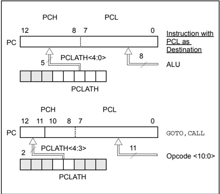
The Program Counter (PC) is 13 bits wide. The low byte comes from the PCL register which is a readable and writable register. The upper bits (PC<12:8>) are not readable, but are indirectly writable through the PCLATH register. On any Reset, the upper bits of the PC will be cleared. Figure 2-5 shows the two situations for the loading of the PC. The upper example in the figure shows how the PC is loaded on a write to PCL (PCLATH<4:0> → PCH). The lower example in the figure shows how the PC is loaded during a CALL or GOTO instruction (PCLATH<4:3> → PCH).
FIGURE 2-5: LOADING OF PC IN DIFFERENT SITUATIONS
2.3.1 COMPUTED GOTO
A computed GOTO is accomplished by adding an offset to the program counter (ADDWF PCL). When doing a table read using a computed GOTO method, care should be exercised if the table location crosses a PCL memory boundary (each 256-byte block). Refer to the application note, AN556, “Implementing a Table Read” (DS00556).
2.3.2 STACK
The PIC16F87XA family has an 8-level deep x 13-bit wide hardware stack. The stack space is not part of either program or data space and the stack pointer is not readable or writable. The PC is PUSHed onto the stack when a CALL instruction is executed, or an interrupt causes a branch. The stack is POP’ed in the event of a RETURN, RETLW or a RETFIE instruction execution. PCLATH is not affected by a PUSH or POP operation.
The stack operates as a circular buffer. This means that after the stack has been PUSHed eight times, the ninth push overwrites the value that was stored from the first push. The tenth push overwrites the second push (and so on).
Note 1: There are no status bits to indicate stack overflow or stack underflow conditions.
2: There are no instructions/mnemonics called PUSH or POP. These are actions that occur from the execution of the CALL, RETURN, RETLW and RETFIE instructions or the vectoring to an interrupt address.
2.4 Program Memory Paging
All PIC16F87XA devices are capable of addressing a continuous 8K word block of program memory. The CALL and GOTO instructions provide only 11 bits of address to allow branching within any 2K program memory page. When doing a CALL or GOTO instruction, the upper 2 bits of the address are provided by PCLATH<4:3>. When doing a CALL or GOTO instruction, the user must ensure that the page select bits are programmed so that the desired program memory page is addressed. If a return from a CALL instruction (or interrupt) is executed, the entire 13-bit PC is popped off the stack. Therefore, manipulation of the PCLATH<4:3> bits is not required for the RETURN instructions (which POPs the address from the stack).
Note: The contents of the PCLATH register are unchanged after a RETURN or RETFIE instruction is executed. The user must rewrite the contents of the PCLATH register for any subsequent subroutine calls or GOTO instructions.
Example 2-1 shows the calling of a subroutine in page 1 of the program memory. This example assumes that PCLATH is saved and restored by the Interrupt Service Routine (if interrupts are used).
EXAMPLE 2-1: CALL OF A SUBROUTINE IN PAGE 1 FROM PAGE 0
ORG 0x500 BCF PCLATH,4 BSF PCLATH,3 ;Select page 1 ; (800h-FFFh) CALL SUB1_P1 ;Call subroutine in : ;page 1 (800h-FFFh) : ORG 0x900 ;page 1 (800h-FFFh) SUB1_P1 : ;called subroutine ;page 1 (800h-FFFh) : RETURN ;return to ;Call subroutine ;in page 0 ; (000h-7FFh)
2.5 Indirect Addressing, INDF and FSR Registers
The INDF register is not a physical register. Addressing the INDF register will cause indirect addressing.
Indirect addressing is possible by using the INDF register. Any instruction using the INDF register actually accesses the register pointed to by the File Select Register, FSR. Reading the INDF register itself, indirectly (FSR = 0) will read 00h. Writing to the INDF register indirectly results in a no operation (although status bits may be affected). An effective 9-bit address is obtained by concatenating the 8-bit FSR register and the IRP bit (Status<7>) as shown in Figure 2-6.
A simple program to clear RAM locations 20h-2Fh using indirect addressing is shown in Example 2-2.
EXAMPLE 2-2: INDIRECT ADDRESSING MOVLW 0x20 ;initialize pointer MOVWF FSR ;to RAM NEXT CLRF INDF ;clear INDF register INCF FSR,F ;inc pointer BTFSS FSR,4 ;all done? GOTO NEXT ;no clear next CONTINUE : ;yes continue
FIGURE 2-6: DIRECT/INDIRECT ADDRESSING
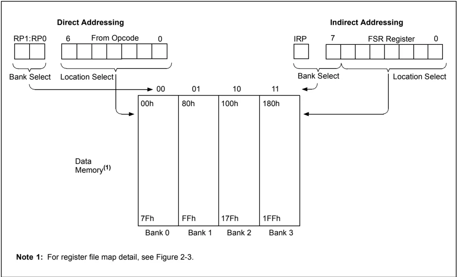
Note 1: For register file map detail, see Figure 2-3.
NOTES: