SLAS735J – APRIL 2011 – REVISED MAY 2013
Pin-Oscillator Frequency – Ports Px
over recommended ranges of supply voltage and operating free-air temperature (unless otherwise noted)
| PARAMETER | TEST CONDITIONS | VCC | MIN | TYP | MAX | UNIT |
|---|---|---|---|---|---|---|
| fOP1.x Port output oscillation frequency | P1.y, CL = 10 pF, RL = 100 kΩ(1)(2) | 3 V | 1400 | kHz | ||
| P1.y, CL = 20 pF, RL = 100 kΩ(1)(2) | 900 | |||||
| fOP2.x Port output oscillation frequency | P2.0 to P2.5, CL = 10 pF, RL = 100 kΩ(1)(2) | 1800 | kHz | |||
| P2.0 to P2.5, CL = 20 pF, RL = 100 kΩ(1)(2) | 3 V | 1000 | ||||
| fOP2.6/7 Port output oscillation frequency | P2.6 and P2.7, CL = 20 pF, RL = 100 kΩ(1)(2) | 3 V | 700 | kHz | ||
| fOP3.x Port output oscillation frequency | P3.y, CL = 10 pF, RL = 100 kΩ(1)(2) | 1800 | kHz | |||
| P3.y, CL = 20 pF, RL = 100 kΩ(1)(2) | 1000 |
(1) A resistive divider with two 50-kΩ resistors between VCC and VSS is used as load. The output is connected to the center tap of the divider.
(2) The output voltage reaches at least 10% and 90% VCC at the specified toggle frequency.
Typical Characteristics, Pin-Oscillator Frequency
TYPICAL OSCILLATING FREQUENCY VS LOAD CAPACITANCE
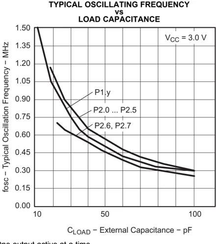
A. One output active at a time. Figure 10.
TYPICAL OSCILLATING FREQUENCY VS LOAD CAPACITANCE
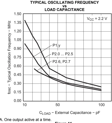
A. One output active at a time. Figure 11.
26 Submit Documentation Feedback Copyright © 2011–2013, Texas Instruments Incorporated
POR, BOR(1)(2)
over recommended ranges of supply voltage and operating free-air temperature (unless otherwise noted)
| PARAMETER | TEST CONDITIONS | VCC | MIN | TYP | MAX | UNIT |
|---|---|---|---|---|---|---|
| VCC(start) | See Figure 12 | dVCC/dt ≤ 3 V/s | 0.7 × V(B_IT–) | V | ||
| V(B_IT–) | See Figure 12 through Figure 14 | dVCC/dt ≤ 3 V/s | 1.35 | V | ||
| Vhys(B_IT–) | See Figure 12 | dVCC/dt ≤ 3 V/s | 140 | mV | ||
| td(BOR) | See Figure 12 | 2000 | μs | |||
| t(reset) | Pulse duration needed at RST/NMI pin to accepted reset internally | 2.2 V | 2 | μs |
(1) The current consumption of the brownout module is already included in the ICC current consumption data. The voltage level V(B_IT–) + Vhys(B_IT–) is ≤ 1.8 V.
(2) During power up, the CPU begins code execution following a period of td(BOR) after VCC = V(B_IT–) + Vhys(B_IT–). The default DCO settings must not be changed until VCC ≥ VCC(min), where VCC(min) is the minimum supply voltage for the desired operating frequency.
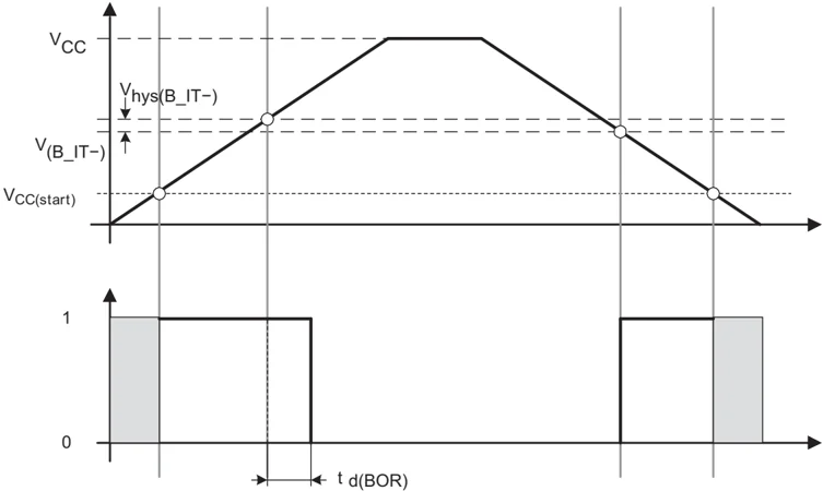
Figure 12. POR and BOR vs Supply Voltage
SLAS735J–APRIL 2011–REVISED MAY 2013
Typical Characteristics, POR and BOR
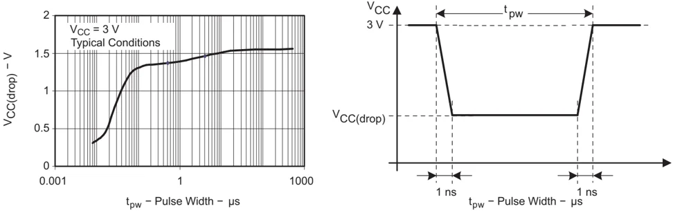
VCC = 3 V Typical Conditions VCC(drop) – V 2 1.5 1 0.5 0 0.001 1 1000 tpw – Pulse Width – µs
VCC 3 V VCC(drop) 1 ns 1 ns tpw – Pulse Width – µs
Figure 13. VCC(drop) Level With a Square Voltage Drop to Generate a POR or BOR Signal
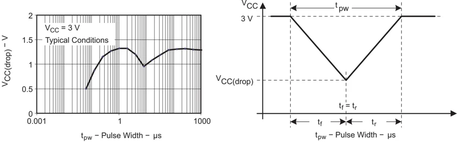
VCC = 3 V Typical Conditions VCC(drop) – V 2 1.5 1 0.5 0 0.001 1 1000 tpw – Pulse Width – µs
VCC 3 V VCC(drop) tf = tr tf tr tpw – Pulse Width – µs
Figure 14. VCC(drop) Level With a Triangle Voltage Drop to Generate a POR or BOR Signal
28 Submit Documentation Feedback Copyright © 2011–2013, Texas Instruments Incorporated
DCO Frequency
over recommended ranges of supply voltage and operating free-air temperature (unless otherwise noted)
| PARAMETER | TEST CONDITIONS | VCC | MIN | TYP | MAX | UNIT |
|---|---|---|---|---|---|---|
| VCC Supply voltage | RSELx < 14 | 1.8 | 3.6 | V | ||
| RSELx = 14 | 2.2 | 3.6 | ||||
| RSELx = 15 | 3 | 3.6 | ||||
| fDCO(0,0) DCO frequency (0, 0) | RSELx = 0, DCOx = 0, MODx = 0 | 3 V | 0.06 | 0.14 | MHz | |
| fDCO(0,3) DCO frequency (0, 3) | RSELx = 0, DCOx = 3, MODx = 0 | 3 V | 0.07 | 0.17 | MHz | |
| fDCO(1,3) DCO frequency (1, 3) | RSELx = 1, DCOx = 3, MODx = 0 | 3 V | 0.15 | MHz | ||
| fDCO(2,3) DCO frequency (2, 3) | RSELx = 2, DCOx = 3, MODx = 0 | 3 V | 0.21 | MHz | ||
| fDCO(3,3) DCO frequency (3, 3) | RSELx = 3, DCOx = 3, MODx = 0 | 3 V | 0.30 | MHz | ||
| fDCO(4,3) DCO frequency (4, 3) | RSELx = 4, DCOx = 3, MODx = 0 | 3 V | 0.41 | MHz | ||
| fDCO(5,3) DCO frequency (5, 3) | RSELx = 5, DCOx = 3, MODx = 0 | 3 V | 0.58 | MHz | ||
| fDCO(6,3) DCO frequency (6, 3) | RSELx = 6, DCOx = 3, MODx = 0 | 3 V | 0.54 | 1.06 | MHz | |
| fDCO(7,3) DCO frequency (7, 3) | RSELx = 7, DCOx = 3, MODx = 0 | 3 V | 0.80 | 1.50 | MHz | |
| fDCO(8,3) DCO frequency (8, 3) | RSELx = 8, DCOx = 3, MODx = 0 | 3 V | 1.6 | MHz | ||
| fDCO(9,3) DCO frequency (9, 3) | RSELx = 9, DCOx = 3, MODx = 0 | 3 V | 2.3 | MHz | ||
| fDCO(10,3) DCO frequency (10, 3) | RSELx = 10, DCOx = 3, MODx = 0 | 3 V | 3.4 | MHz | ||
| fDCO(11,3) DCO frequency (11, 3) | RSELx = 11, DCOx = 3, MODx = 0 | 3 V | 4.25 | MHz | ||
| fDCO(12,3) DCO frequency (12, 3) | RSELx = 12, DCOx = 3, MODx = 0 | 3 V | 4.30 | 7.30 | MHz | |
| fDCO(13,3) DCO frequency (13, 3) | RSELx = 13, DCOx = 3, MODx = 0 | 3 V | 6.00 | 7.8 | 9.60 | MHz |
| fDCO(14,3) DCO frequency (14, 3) | RSELx = 14, DCOx = 3, MODx = 0 | 3 V | 8.60 | 13.9 | MHz | |
| fDCO(15,3) DCO frequency (15, 3) | RSELx = 15, DCOx = 3, MODx = 0 | 3 V | 12.0 | 18.5 | MHz | |
| fDCO(15,7) DCO frequency (15, 7) | RSELx = 15, DCOx = 7, MODx = 0 | 3 V | 16.0 | 26.0 | MHz | |
| SRSEL Frequency step between range RSEL and RSEL+1 | SRSEL = fDCO(RSEL+1,DCO)/fDCO(RSEL,DCO) | 3 V | 1.35 | ratio | ||
| SDCO Frequency step between tap DCO and DCO+1 | SDCO = fDCO(RSEL,DCO+1)/fDCO(RSEL,DCO) | 3 V | 1.08 | ratio | ||
| Duty cycle | Measured at SMCLK output | 3 V | 50 | % |
SLAS735J – APRIL 2011 – REVISED MAY 2013
Calibrated DCO Frequencies, Tolerance
over recommended ranges of supply voltage and operating free-air temperature (unless otherwise noted)
| PARAMETER | TEST CONDITIONS | TA | VCC | MIN | TYP | MAX | UNIT |
|---|---|---|---|---|---|---|---|
| 1-MHz tolerance over temperature(1) | BCSC1 = CALBC1_1MHZ, DCOCTL = CALDCO_1MHZ, calibrated at 30°C and 3 V | 0°C to 85°C | 3 V | -3 | ±0.5 | +3 | % |
| 1-MHz tolerance over VCC | BCSC1 = CALBC1_1MHZ, DCOCTL = CALDCO_1MHZ, calibrated at 30°C and 3 V | 30°C | 1.8 V to 3.6 V | -3 | ±2 | +3 | % |
| 1-MHz tolerance overall | BCSC1 = CALBC1_1MHZ, DCOCTL = CALDCO_1MHZ, calibrated at 30°C and 3 V | -40°C to 85°C | 1.8 V to 3.6 V | -6 | ±3 | +6 | % |
| 8-MHz tolerance over temperature(1) | BCSC1 = CALBC1_8MHZ, DCOCTL = CALDCO_8MHZ, calibrated at 30°C and 3 V | 0°C to 85°C | 3 V | -3 | ±0.5 | +3 | % |
| 8-MHz tolerance over VCC | BCSC1 = CALBC1_8MHZ, DCOCTL = CALDCO_8MHZ, calibrated at 30°C and 3 V | 30°C | 2.2 V to 3.6 V | -3 | ±2 | +3 | % |
| 8-MHz tolerance overall | BCSC1 = CALBC1_8MHZ, DCOCTL = CALDCO_8MHZ, calibrated at 30°C and 3 V | -40°C to 85°C | 2.2 V to 3.6 V | -6 | ±3 | +6 | % |
| 12-MHz tolerance over temperature(1) | BCSC1 = CALBC1_12MHZ, DCOCTL = CALDCO_12MHZ, calibrated at 30°C and 3 V | 0°C to 85°C | 3 V | -3 | ±0.5 | +3 | % |
| 12-MHz tolerance over VCC | BCSC1 = CALBC1_12MHZ, DCOCTL = CALDCO_12MHZ, calibrated at 30°C and 3 V | 30°C | 2.7 V to 3.6 V | -3 | ±2 | +3 | % |
| 12-MHz tolerance overall | BCSC1 = CALBC1_12MHZ, DCOCTL = CALDCO_12MHZ, calibrated at 30°C and 3 V | -40°C to 85°C | 2.7 V to 3.6 V | -6 | ±3 | +6 | % |
| 16-MHz tolerance over temperature(1) | BCSC1 = CALBC1_16MHZ, DCOCTL = CALDCO_16MHZ, calibrated at 30°C and 3 V | 0°C to 85°C | 3 V | -3 | ±0.5 | +3 | % |
| 16-MHz tolerance over VCC | BCSC1 = CALBC1_16MHZ, DCOCTL = CALDCO_16MHZ, calibrated at 30°C and 3 V | 30°C | 3.3 V to 3.6 V | -3 | ±2 | +3 | % |
| 16-MHz tolerance overall | BCSC1 = CALBC1_16MHZ, DCOCTL = CALDCO_16MHZ, calibrated at 30°C and 3 V | -40°C to 85°C | 3.3 V to 3.6 V | -6 | ±3 | +6 | % |
(1) This is the frequency change from the measured frequency at 30°C over temperature.
30 Submit Documentation Feedback Copyright © 2011–2013, Texas Instruments Incorporated
MSP430G2x53
MSP430G2x13
www.ti.com SLAS735J–APRIL 2011–REVISED MAY 2013
Wake-Up From Lower-Power Modes (LPM3/4)
over recommended ranges of supply voltage and operating free-air temperature (unless otherwise noted)
\begin{tabular}{|l|l|l|l|l|l|l|} \hline PARAMETER & TEST CONDITIONS & VCC & MIN & TYP & MAX & UNIT \ \hline tDCO,LPM3/4 DCO clock wake-up time from LPM3/4$^{(1)} & BCSCTL1 = CALBC1_1MHz, DCOCTL = CALDCO_1MHz & 3 V & & 1.5 & & \mu$s \ \hline tCPU,LPM3/4 CPU wake-up time from LPM3/4$^{(2)}$ & & & & 1/fMCLK + tClock,LPM3/4 & & \ \hline \end{tabular}
(1) The DCO clock wake-up time is measured from the edge of an external wake-up signal (e.g., port interrupt) to the first clock edge observable externally on a clock pin (MCLK or SMCLK). (2) Parameter applicable only if DCOCLK is used for MCLK.
Typical Characteristics, DCO Clock Wake-Up Time From LPM3/4
 Figure 15. DCO Wake-Up Time From LPM3 vs DCO Frequency
Copyright © 2011–2013, Texas Instruments Incorporated Submit Documentation Feedback 31
SLAS735J – APRIL 2011 – REVISED MAY 2013
Crystal Oscillator, XT1, Low-Frequency Mode(1)
over recommended ranges of supply voltage and operating free-air temperature (unless otherwise noted)
| PARAMETER | TEST CONDITIONS | VCC | MIN | TYP | MAX | UNIT | |
|---|---|---|---|---|---|---|---|
| fLFX T1,LF | LFX T1 oscillator crystal frequency, LF mode 0, 1 | XTS = 0, LFX T1Sx = 0 or 1 | 1.8 V to 3.6 V | 32768 | Hz | ||
| fLFX T1,LF,logic | LFX T1 oscillator logic level square wave input frequency, LF mode | XTS = 0, XCAPx = 0, LFX T1Sx = 3 | 1.8 V to 3.6 V | 10000 | 32768 | 50000 | Hz |
| OALF | Oscillation allowance for LF crystals | XTS = 0, LFX T1Sx = 0, fLFX T1,LF = 32768 Hz, CL,eff = 6 pF | 500 | kΩ | |||
| XTS = 0, LFX T1Sx = 0, fLFX T1,LF = 32768 Hz, CL,eff = 12 pF | 200 | ||||||
| CL,eff | Integrated effective load capacitance, LF mode(2) | XTS = 0, XCAPx = 0 | 1 | pF | |||
| XTS = 0, XCAPx = 1 | 5.5 | ||||||
| XTS = 0, XCAPx = 2 | 8.5 | ||||||
| XTS = 0, XCAPx = 3 | 11 | ||||||
| Duty cycle, LF mode | XTS = 0, Measured at P2.0/ACLK, fLFX T1,LF = 32768 Hz | 2.2 V | 30 | 50 | 70 | % | |
| fFault,LF | Oscillator fault frequency, LF mode(3) | XTS = 0, XCAPx = 0, LFX T1Sx = 3(4) | 2.2 V | 10 | 10000 | Hz |
(1) To improve EMI on the XT1 oscillator, the following guidelines should be observed. (a) Keep the trace between the device and the crystal as short as possible. (b) Design a good ground plane around the oscillator pins. (c) Prevent crosstalk from other clock or data lines into oscillator pins XIN and XOUT. (d) Avoid running PCB traces underneath or adjacent to the XIN and XOUT pins. (e) Use assembly materials and process that avoid any parasitic load on the oscillator XIN and XOUT pins. (f) If a conformal coating is used, ensure that it does not induce capacitive or resistive leakage between the oscillator pins. (g) Do not route the XOUT line to the JTAG header to support the serial programming adapter as shown in other documentation. This signal is no longer required for the serial programming adapter. (2) Includes parasitic bond and package capacitance (approximately 2 pF per pin). Because the PCB adds additional capacitance, it is recommended to verify the correct load by measuring the ACLK frequency. For a correct setup, the effective load capacitance should always match the specification of the used crystal. (3) Frequencies below the MIN specification set the fault flag. Frequencies above the MAX specification do not set the fault flag. Frequencies in between might set the flag. (4) Measured with logic-level input frequency but also applies to operation with crystals.
Internal Very-Low-Power Low-Frequency Oscillator (VLO)
over recommended ranges of supply voltage and operating free-air temperature (unless otherwise noted)
| PARAMETER | TA | VCC | MIN | TYP | MAX | UNIT | |
|---|---|---|---|---|---|---|---|
| fVLO | VLO frequency | -40°C to 85°C | 3 V | 4 | 12 | 20 | kHz |
| dfVLO/dT | VLO frequency temperature drift | -40°C to 85°C | 3 V | 0.5 | %/°C | ||
| dfVLO/dVCC | VLO frequency supply voltage drift | 25°C | 1.8 V to 3.6 V | 4 | %/V |
Timer_A
over recommended ranges of supply voltage and operating free-air temperature (unless otherwise noted)
| PARAMETER | TEST CONDITIONS | VCC | MIN | TYP | MAX | UNIT | |
|---|---|---|---|---|---|---|---|
| fTA | Timer_A input clock frequency | SMCLK, duty cycle = 50% ± 10% | fSYSTEM | MHz | |||
| tTA,cap | Timer_A capture timing | TA0, TA1 | 3 V | 20 | ns |
32 Submit Documentation Feedback Copyright © 2011–2013, Texas Instruments Incorporated
USCI (UART Mode)
over recommended ranges of supply voltage and operating free-air temperature (unless otherwise noted)
| PARAMETER | TEST CONDITIONS | VCC | MIN | TYP | MAX | UNIT |
|---|---|---|---|---|---|---|
| fUSCI | USCI input clock frequency | SMCLK, duty cycle = 50% ± 10% | fSYSTEM | MHz | ||
| fmax,BITCLK | Maximum BITCLK clock frequency (equals baudrate in MBaud)(1) | 3 V | 2 | MHz | ||
| tr | UART receive deglitch time(2) | 3 V | 50 | 100 | 600 ns |
(1) The DCO wake-up time must be considered in LPM3 and LPM4 for baud rates above 1 MHz.
(2) Pulses on the UART receive input (UCxRX) shorter than the UART receive deglitch time are suppressed. To ensure that pulses are correctly recognized, their duration should exceed the maximum specification of the deglitch time.
USCI (SPI Master Mode)
over recommended ranges of supply voltage and operating free-air temperature (unless otherwise noted) (see Figure 16 and Figure 17)
| PARAMETER | TEST CONDITIONS | VCC | MIN | TYP | MAX | UNIT |
|---|---|---|---|---|---|---|
| fUSCI | USCI input clock frequency | SMCLK, duty cycle = 50% ± 10% | fSYSTEM | MHz | ||
| tSU,MI | SOMI input data setup time | 3 V | 75 | ns | ||
| tHD,MI | SOMI input data hold time | 3 V | 0 | ns | ||
| tVALID,MO | SIMO output data valid time | UCLK edge to SIMO valid, CL = 20 pF | 3 V | 20 ns |
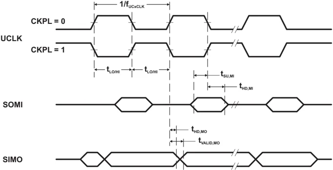
Figure 16. SPI Master Mode, CKPH = 0
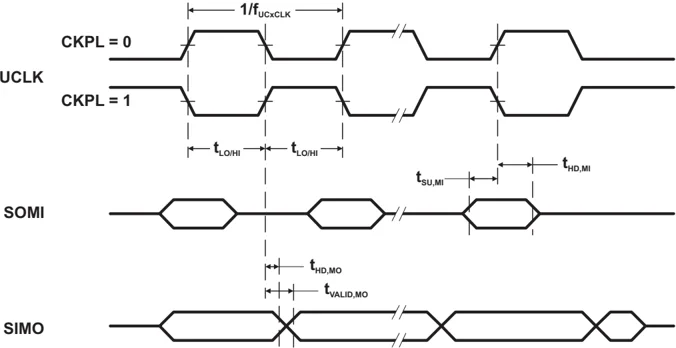
Figure 17. SPI Master Mode, CKPH = 1
SLAS735J–APRIL 2011–REVISED MAY 2013
USCI (SPI Slave Mode)
over recommended ranges of supply voltage and operating free-air temperature (unless otherwise noted) (see Figure 18 and Figure 19)
| PARAMETER | TEST CONDITIONS | VCC | MIN | TYP | MAX | UNIT | |
|---|---|---|---|---|---|---|---|
| tSTE,LEAD | STE lead time, STE low to clock | 3 V | 50 | ns | |||
| tSTE,LAG | STE lag time, Last clock to STE high | 3 V | 10 | ns | |||
| tSTE,ACC | STE access time, STE low to SOMI data out | 3 V | 50 | ns | |||
| tSTE,DIS | STE disable time, STE high to SOMI high impedance | 3 V | 50 | ns | |||
| tSU,SI | SIMO input data setup time | 3 V | 15 | ns | |||
| tHD,SI | SIMO input data hold time | 3 V | 10 | ns | |||
| tVALID,SO | SOMI output data valid time | UCLK edge to SOMI valid, CL = 20 pF | 3 V | 50 | 75 | ns |
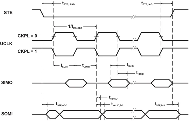
Figure 18. SPI Slave Mode, CKPH = 0
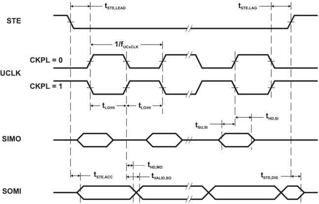
Figure 19. SPI Slave Mode, CKPH = 1
34 Submit Documentation Feedback Copyright © 2011–2013, Texas Instruments Incorporated
USCI (I2C Mode)
over recommended ranges of supply voltage and operating free-air temperature (unless otherwise noted) (see Figure 20)
| PARAMETER | TEST CONDITIONS | VCC | MIN | TYP | MAX | UNIT | |
|---|---|---|---|---|---|---|---|
| fUSCI | USCI input clock frequency | SMCLK, duty cycle = 50% ± 10% | fSYSTEM | MHz | |||
| fSCL | SCL clock frequency | 3 V | 0 | 400 | kHz | ||
| tHD,STA | Hold time (repeated) START | fSCL ≤ 100 kHz | 3 V | 4.0 | μs | ||
| fSCL > 100 kHz | 3 V | 0.6 | |||||
| tSU,STA | Setup time for a repeated START | fSCL ≤ 100 kHz | 3 V | 4.7 | μs | ||
| fSCL > 100 kHz | 3 V | 0.6 | |||||
| tHD,DAT | Data hold time | 3 V | 0 | ns | |||
| tSU,DAT | Data setup time | 3 V | 250 | ns | |||
| tSU,STO | Setup time for STOP | 3 V | 4.0 | μs | |||
| tSP | Pulse width of spikes suppressed by input filter | 3 V | 50 | 100 | 600 | ns |
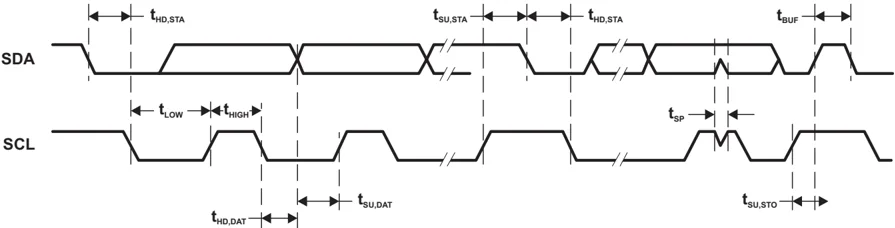
Figure 20. I2C Mode Timing
Comparator_A+
over recommended ranges of supply voltage and operating free-air temperature (unless otherwise noted)
| PARAMETER | TEST CONDITIONS | VCC | MIN | TYP | MAX | UNIT |
|---|---|---|---|---|---|---|
| I(DD)(1) | CAON = 1, CARSEL = 0, CAREF = 0 | 3 V | 45 | μA | ||
| I(Refladder/RefDiode) | CAON = 1, CARSEL = 0, CAREF = 1, 2, or 3, No load at CA0 and CA1 | 3 V | 45 | μA | ||
| V(IC) | Common-mode input voltage | CAON = 1 | 3 V | 0 | VCC-1 | V |
| V(Ref025) | (Voltage at 0.25 VCC node) / VCC | PCA0 = 1, CARSEL = 1, CAREF = 1, No load at CA0 and CA1 | 3 V | 0.24 | ||
| V(Ref050) | (Voltage at 0.5 VCC node) / VCC | PCA0 = 1, CARSEL = 1, CAREF = 2, No load at CA0 and CA1 | 3 V | 0.48 | ||
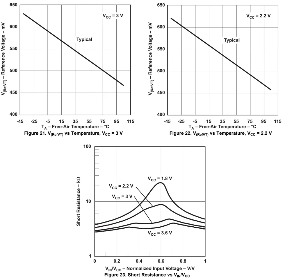
| V(RefVT) | See Figure 21 and Figure 22 | PCA0 = 1, CARSEL = 1, CAREF = 3, No load at CA0 and CA1, TA = 85°C | 3 V | 490 | mV | |
| V(offset) | Offset voltage(2) | 3 V | ±10 | mV | ||
| Vhys | Input hysteresis | CAON = 1 | 3 V | 0.7 | mV | |
| t(response) | Response time (low-high and high-low) | TA = 25°C, Overdrive 10 mV, Without filter: CAF = 0 | 3 V | 120 | ns | |
| TA = 25°C, Overdrive 10 mV, With filter: CAF = 1 | 3 V | 1.5 | μs |
(1) The leakage current for the Comparator_A+ terminals is identical to Ikg(Px.y) specification.
(2) The input offset voltage can be cancelled by using the CAEX bit to invert the Comparator_A+ inputs on successive measurements. The two successive measurements are then summed together.
SLAS735J–APRIL 2011–REVISED MAY 2013
Typical Characteristics – Comparator_A+
Figure 21. V(RefVT) vs Temperature, VCC = 3 V
Figure 22. V(RefVT) vs Temperature, VCC = 2.2 V
Figure 23. Short Resistance vs VIN/VCC
36 Submit Documentation Feedback Copyright © 2011–2013, Texas Instruments Incorporated
10-Bit ADC, Power Supply and Input Range Conditions (MSP430G2x53 Only)
over recommended ranges of supply voltage and operating free-air temperature (unless otherwise noted) (1)
| PARAMETER | TEST CONDITIONS | TA | VCC | MIN | TYP | MAX | UNIT |
|---|---|---|---|---|---|---|---|
| VCC Analog supply voltage | VSS = 0 V | 2.2 | 3.6 | V | |||
| VAx Analog input voltage (2) | All Ax terminals, Analog inputs selected in ADC10AE register | 3 V | 0 | VCC | V | ||
| IADC10 ADC10 supply current (3) | fADC10CLK = 5.0 MHz, ADC10ON = 1, REFON = 0, ADC10SHT0 = 1, ADC10SHT1 = 0, ADC10DIV = 0 | 25°C | 3 V | 0.6 | mA | ||
| IREF+ Reference supply current, reference buffer disabled (4) | fADC10CLK = 5.0 MHz, ADC10ON = 0, REF2_5V = 0, REFON = 1, REFOUT = 0 | 25°C | 3 V | 0.25 | mA | ||
| fADC10CLK = 5.0 MHz, ADC10ON = 0, REF2_5V = 1, REFON = 1, REFOUT = 0 | 0.25 | ||||||
| IREFB,0 Reference buffer supply current with ADC10SR = 0 (4) | fADC10CLK = 5.0 MHz, ADC10ON = 0, REFON = 1, REF2_5V = 0, REFOUT = 1, ADC10SR = 0 | 25°C | 3 V | 1.1 | mA | ||
| IREFB,1 Reference buffer supply current with ADC10SR = 1 (4) | fADC10CLK = 5.0 MHz, ADC10ON = 0, REFON = 1, REF2_5V = 0, REFOUT = 1, ADC10SR = 1 | 25°C | 3 V | 0.5 | mA | ||
| CI Input capacitance | Only one terminal Ax can be selected at one time | 25°C | 3 V | 27 | pF | ||
| RI Input MUX ON resistance | 0 V ≤ VAx ≤ VCC | 25°C | 3 V | 1000 | Ω |
(1) The leakage current is defined in the leakage current table with Px.y/Ax parameter.
(2) The analog input voltage range must be within the selected reference voltage range VR+ to VR– for valid conversion results.
(3) The internal reference supply current is not included in current consumption parameter IADC10.
(4) The internal reference current is supplied via terminal VCC. Consumption is independent of the ADC10ON control bit, unless a conversion is active. The REFON bit enables the built-in reference to settle before starting an A/D conversion.
SLAS735J – APRIL 2011 – REVISED MAY 2013
10-Bit ADC, Built-In Voltage Reference (MSP430G2x53 Only)
over recommended ranges of supply voltage and operating free-air temperature (unless otherwise noted)
| PARAMETER | TEST CONDITIONS | VCC | MIN | TYP | MAX | UNIT |
|---|---|---|---|---|---|---|
| VCC,REF+ Positive built-in reference analog supply voltage range | IVREF+ ≤ 1 mA, REF2_5V = 0 | 2.2 | V | |||
| IVREF+ ≤ 1 mA, REF2_5V = 1 | 2.9 | |||||
| VREF+ Positive built-in reference voltage | IVREF+ ≤ IVREF+max, REF2_5V = 0 | 3 V | 1.41 | 1.5 | 1.59 | V |
| IVREF+ ≤ IVREF+max, REF2_5V = 1 | 3 V | 2.35 | 2.5 | 2.65 | ||
| ILD,VREF+ Maximum VREF+ load current | 3 V | ±1 | mA | |||
| VREF+ load regulation | IVREF+ = 500 μA ± 100 μA, Analog input voltage VAx ≠ 0.75 V, REF2_5V = 0 | 3 V | ±2 | LSB | ||
| IVREF+ = 500 μA ± 100 μA, Analog input voltage VAx ≠ 1.25 V, REF2_5V = 1 | 3 V | ±2 | ||||
| VREF+ load regulation response time | IVREF+ = 100 μA→900 μA, VAx ≠ 0.5 × VREF+, Error of conversion result ≤ 1 LSB, ADC10SR = 0 | 3 V | 400 | ns | ||
| CVREF+ Maximum capacitance at pin VREF+ | IVREF+ ≤ ±1 mA, REFON = 1, REFOUT = 1 | 3 V | 100 | pF | ||
| TCREF+ Temperature coefficient(1) | IVREF+ = const with 0 mA ≤ IVREF+ ≤ 1 mA | 3 V | ±100 | ppm/°C | ||
| tREFON Settling time of internal reference voltage to 99.9% VREF | IVREF+ = 0.5 mA, REF2_5V = 0, REFON = 0 → 1 | 3.6 V | 30 | μs | ||
| tREFBURST Settling time of reference buffer to 99.9% VREF | IVREF+ = 0.5 mA, REF2_5V = 1, REFON = 1, REFBURST = 1, ADC10SR = 0 | 3 V | 2 | μs |
(1) Calculated using the box method: (MAX(-40 to 85°C) – MIN(-40 to 85°C)) / MIN(-40 to 85°C) / (85°C – (–40°C))
38 Submit Documentation Feedback
Copyright © 2011–2013, Texas Instruments Incorporated
10-Bit ADC, External Reference(1) (MSP430G2x53 Only)
over recommended ranges of supply voltage and operating free-air temperature (unless otherwise noted)
| PARAMETER | TEST CONDITIONS | VCC | MIN | TYP | MAX | UNIT |
|---|---|---|---|---|---|---|
| VEREF+ Positive external reference input voltage range (2) | VREF+ > VREF–, SREF1 = 1, SREF0 = 0 | 1.4 | VCC | V | ||
| VREF– ≤ VREF+ ≤ VCC – 0.15 V, SREF1 = 1, SREF0 = 1 (3) | 1.4 | 3 | V | |||
| VEREF– Negative external reference input voltage range (4) | VREF+ > VREF– | 0 | 1.2 | V | ||
| ΔVEREF Differential external reference input voltage range, ΔVEREF = VREF+ – VREF– | VREF+ > VREF– (5) | 1.4 | VCC | V | ||
| IVEREF+ Static input current into VREF+ | 0 V ≤ VREF+ ≤ VCC, SREF1 = 1, SREF0 = 0 | 3 V | ±1 | μA | ||
| 0 V ≤ VREF+ ≤ VCC – 0.15 V ≤ 3 V, SREF1 = 1, SREF0 = 1 (3) | 3 V | 0 | μA | |||
| IVEREF– Static input current into VREF– | 0 V ≤ VREF– ≤ VCC | 3 V | ±1 | μA |
(1) The external reference is used during conversion to charge and discharge the capacitance array. The input capacitance, CI, is also the dynamic load for an external reference during conversion. The dynamic impedance of the reference supply should follow the recommendations on analog-source impedance to allow the charge to settle for 10-bit accuracy.
(2) The accuracy limits the minimum positive external reference voltage. Lower reference voltage levels may be applied with reduced accuracy requirements.
(3) Under this condition the external reference is internally buffered. The reference buffer is active and requires the reference buffer supply current IREFB. The current consumption can be limited to the sample and conversion period with REBURST = 1.
(4) The accuracy limits the maximum negative external reference voltage. Higher reference voltage levels may be applied with reduced accuracy requirements.
(5) The accuracy limits the minimum external differential reference voltage. Lower differential reference voltage levels may be applied with reduced accuracy requirements.
10-Bit ADC, Timing Parameters (MSP430G2x53 Only)
over recommended ranges of supply voltage and operating free-air temperature (unless otherwise noted)
| PARAMETER | TEST CONDITIONS | VCC | MIN | TYP | MAX | UNIT |
|---|---|---|---|---|---|---|
| fADC10CLK ADC10 input clock frequency | For specified performance of ADC10 linearity parameters | 3 V | 0.45 | 6.3 | MHz | |
| ADC10SR = 0 | ||||||
| ADC10SR = 1 | 0.45 | 1.5 | MHz | |||
| fADC10OSC ADC10 built-in oscillator frequency | ADC10DIVx = 0, ADC10SSELx = 0, fADC10CLK = fADC10OSC | 3 V | 3.7 | 6.3 | MHz | |
| tCONVERT Conversion time | ADC10 built-in oscillator, ADC10SSELx = 0, fADC10CLK = fADC10OSC | 3 V | 2.06 | 3.51 | μs | |
| fADC10CLK from ACLK, MCLK, or SMCLK: ADC10SSELx ≠ 0 | 13 × ADC10DIV × 1/fADC10CLK | μs | ||||
| tADC10ON Turn-on settling time of the ADC | (1) | 100 | ns |
(1) The condition is that the error in a conversion started after tADC10ON is less than ±0.5 LSB. The reference and input signal are already settled.
10-Bit ADC, Linearity Parameters (MSP430G2x53 Only)
over recommended ranges of supply voltage and operating free-air temperature (unless otherwise noted)
| PARAMETER | TEST CONDITIONS | VCC | MIN | TYP | MAX | UNIT |
|---|---|---|---|---|---|---|
| EI Integral linearity error | 3 V | ±1 | LSB | |||
| ED Differential linearity error | 3 V | ±1 | LSB | |||
| EO Offset error | Source impedance RS < 100 Ω | 3 V | ±1 | LSB | ||
| EG Gain error | 3 V | ±1.1 | ±2 | LSB | ||
| ET Total unadjusted error | 3 V | ±2 | ±5 | LSB |
SLAS735J – APRIL 2011 – REVISED MAY 2013
10-Bit ADC, Temperature Sensor and Built-In VMID (MSP430G2x53 Only)
over recommended ranges of supply voltage and operating free-air temperature (unless otherwise noted)
| PARAMETER | TEST CONDITIONS | VCC | MIN | TYP | MAX | UNIT |
|---|---|---|---|---|---|---|
| ISENSOR Temperature sensor supply current(1) | REFON = 0, INCHx = 0Ah, TA = 25°C | 3 V | 60 | μA | ||
| TCSENSOR | ADC10ON = 1, INCHx = 0Ah(2) | 3 V | 3.55 | mV/°C | ||
| tSensor(sample) Sample time required if channel 10 is selected(3) | ADC10ON = 1, INCHx = 0Ah, Error of conversion result ≤ 1 LSB | 3 V | 30 | μs | ||
| IVMID Current into divider at channel 11 | ADC10ON = 1, INCHx = 0Bh | 3 V | (4) | μA | ||
| VMID VCC divider at channel 11 | ADC10ON = 1, INCHx = 0Bh, VMID ≠ 0.5 × VCC | 3 V | 1.5 | V | ||
| tVMID(sample) Sample time required if channel 11 is selected(5) | ADC10ON = 1, INCHx = 0Bh, Error of conversion result ≤ 1 LSB | 3 V | 1220 | ns |
(1) The sensor current ISENSOR is consumed if (ADC10ON = 1 and REFON = 1) or (ADC10ON = 1 and INCH = 0Ah and sample signal is high). When REFON = 1, ISENSOR is included in IREF+. When REFON = 0, ISENSOR applies during conversion of the temperature sensor input (INCH = 0Ah).
(2) The following formula can be used to calculate the temperature sensor output voltage:
VSensor,typ = TCSensor (273 + T [°C] ) + VOffset,sensor [mV] or
VSensor,typ = TCSensor T [°C] + VSensor(TA = 0°C) [mV]
(3) The typical equivalent impedance of the sensor is 51 kΩ. The sample time required includes the sensor-on time tSENSOR(on).
(4) No additional current is needed. The VMID is used during sampling.
(5) The on-time tVMID(on) is included in the sampling time tVMID(sample); no additional on time is needed.
Flash Memory
over recommended ranges of supply voltage and operating free-air temperature (unless otherwise noted)
| PARAMETER | TEST CONDITIONS | VCC | MIN | TYP | MAX | UNIT |
|---|---|---|---|---|---|---|
| VCC(PGM/ERASE) Program and erase supply voltage | 2.2 | 3.6 | V | |||
| fFTG Flash timing generator frequency | 257 | 476 | kHz | |||
| IPGM Supply current from VCC during program | 2.2 V, 3.6 V | 1 | 5 | mA | ||
| IERASE Supply current from VCC during erase | 2.2 V, 3.6 V | 1 | 7 | mA | ||
| tCPT Cumulative program time(1) | 2.2 V, 3.6 V | 10 | ms | |||
| tCMErase Cumulative mass erase time | 2.2 V, 3.6 V | 20 | ms | |||
| Program/erase endurance | 104 | 105 | cycles | |||
| tRetention Data retention duration | TJ = 25°C | 100 | years | |||
| tWord Word or byte program time | (2) | 30 | tFTG | |||
| tBlock, 0 Block program time for first byte or word | (2) | 25 | tFTG | |||
| tBlock, 1-63 Block program time for each additional byte or word | (2) | 18 | tFTG | |||
| tBlock, End Block program end-sequence wait time | (2) | 6 | tFTG | |||
| tMass Erase Mass erase time | (2) | 10593 | tFTG | |||
| tSeg Erase Segment erase time | (2) | 4819 | tFTG |
(1) The cumulative program time must not be exceeded when writing to a 64-byte flash block. This parameter applies to all programming methods: individual word/byte write and block write modes.
(2) These values are hardwired into the Flash Controller's state machine (tFTG = 1/fFTG).
40 Submit Documentation Feedback Copyright © 2011–2013, Texas Instruments Incorporated
RAM
over recommended ranges of supply voltage and operating free-air temperature (unless otherwise noted)
| PARAMETER | TEST CONDITIONS | MIN | MAX | UNIT |
|---|---|---|---|---|
| V(RAMh) RAM retention supply voltage (1) | CPU halted | 1.6 | V |
(1) This parameter defines the minimum supply voltage VCC when the data in RAM remains unchanged. No program execution should happen during this supply voltage condition.
JTAG and Spy-Bi-Wire Interface
over recommended ranges of supply voltage and operating free-air temperature (unless otherwise noted)
| PARAMETER | TEST CONDITIONS | VCC | MIN | TYP | MAX | UNIT |
|---|---|---|---|---|---|---|
| fSBW Spy-Bi-Wire input frequency | 2.2 V | 0 | 20 | MHz | ||
| tSBW,Low Spy-Bi-Wire low clock pulse duration | 2.2 V | 0.025 | 15 | μs | ||
| tSBW,En Spy-Bi-Wire enable time (TEST high to acceptance of first clock edge(1)) | 2.2 V | 1 | μs | |||
| tSBW,Ret Spy-Bi-Wire return to normal operation time | 2.2 V | 15 | 100 | μs | ||
| fTCK TCK input frequency(2) | 2.2 V | 0 | 5 | MHz | ||
| RInternal Internal pulldown resistance on TEST | 2.2 V | 25 | 60 | 90 | kΩ |
(1) Tools accessing the Spy-Bi-Wire interface need to wait for the maximum tSBW,En time after pulling the TEST/SBWTCK pin high before applying the first SBWTCK clock edge.
(2) fTCK may be restricted to meet the timing requirements of the module selected.
JTAG Fuse(1)
over recommended ranges of supply voltage and operating free-air temperature (unless otherwise noted)
| PARAMETER | TEST CONDITIONS | MIN | MAX | UNIT |
|---|---|---|---|---|
| VCC(FB) Supply voltage during fuse-blow condition | TA = 25°C | 2.5 | V | |
| VFB Voltage level on TEST for fuse blow | 6 | 7 | V | |
| IFB Supply current into TEST during fuse blow | 100 | mA | ||
| tFB Time to blow fuse | 1 | ms |
(1) Once the fuse is blown, no further access to the JTAG/Test, Spy-Bi-Wire, and emulation feature is possible, and JTAG is switched to bypass mode.
TEXAS INSTRUMENTS
SLAS735J–APRIL 2011–REVISED MAY 2013
PORT SCHEMATICS
Port P1 Pin Schematic: P1.0 to P1.2, Input/Output With Schmitt Trigger
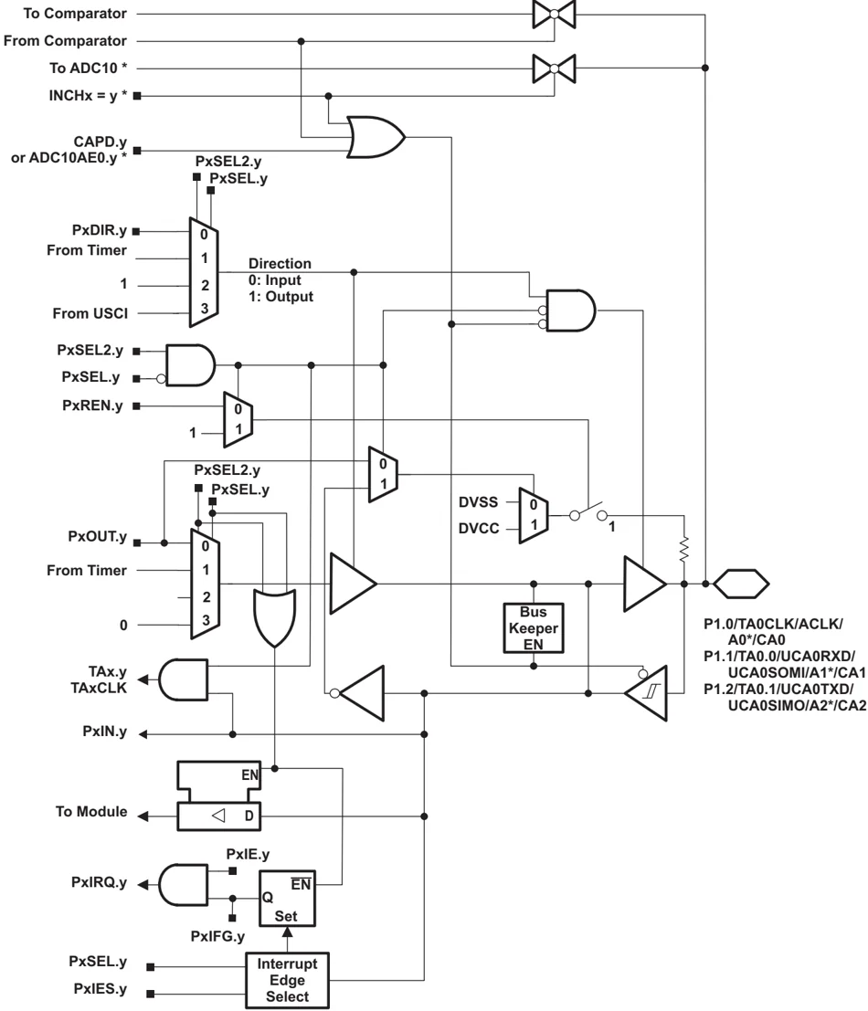
- Note: MSP430G2x53 devices only. MSP430G2x13 devices have no ADC10.
42 Submit Documentation Feedback Copyright © 2011–2013, Texas Instruments Incorporated
Table 16. Port P1 (P1.0 to P1.2) Pin Functions
| PIN NAME (P1.x) | x | FUNCTION | CONTROL BITS AND SIGNALS(1) | ||||
|---|---|---|---|---|---|---|---|
| P1DIR.x | P1SEL.x | P1SEL2.x | ADC10AE.x INCH.x=1(2) | CAPD.y | |||
| P1.0/ TA0CLK/ ACLK/ A0(2)/ CA0/ Pin Osc | 0 | P1.x (I/O) | I: 0; O: 1 | 0 | 0 | 0 | 0 |
| TA0.TACLK | 0 | 1 | 0 | 0 | 0 | ||
| ACLK | 1 | 1 | 0 | 0 | 0 | ||
| A0 | X | X | X | 1 (y = 0) | 0 | ||
| CA0 | X | X | X | 0 | 1 (y = 0) | ||
| Capacitive sensing | X | 0 | 1 | 0 | 0 | ||
| P1.1/ TA0.0/ UCA0RXD/ UCA0SOMI/ A1(2)/ CA1/ Pin Osc | 1 | P1.x (I/O) | I: 0; O: 1 | 0 | 0 | 0 | 0 |
| TA0.0 | 1 | 1 | 0 | 0 | 0 | ||
| TA0.CCI0A | 0 | 1 | 0 | 0 | 0 | ||
| UCA0RXD | from USCI | 1 | 1 | 0 | 0 | ||
| UCA0SOMI | from USCI | 1 | 1 | 0 | 0 | ||
| A1 | X | X | X | 1 (y = 1) | 0 | ||
| CA1 | X | X | X | 0 | 1 (y = 1) | ||
| Capacitive sensing | X | 0 | 1 | 0 | 0 | ||
| P1.2/ TA0.1/ UCA0TXD/ UCA0SIMO/ A2(2)/ CA2/ Pin Osc | 2 | P1.x (I/O) | I: 0; O: 1 | 0 | 0 | 0 | 0 |
| TA0.1 | 1 | 1 | 0 | 0 | 0 | ||
| TA0.CCI1A | 0 | 1 | 0 | 0 | 0 | ||
| UCA0TXD | from USCI | 1 | 1 | 0 | 0 | ||
| UCA0SIMO | from USCI | 1 | 1 | 0 | 0 | ||
| A2 | X | X | X | 1 (y = 2) | 0 | ||
| CA2 | X | X | X | 0 | 1 (y = 2) | ||
| Capacitive sensing | X | 0 | 1 | 0 | 0 |
(1) X = don't care (2) MSP430G2x53 devices only
TEXAS INSTRUMENTS
SLAS735J–APRIL 2011–REVISED MAY 2013 www.ti.com
Port P1 Pin Schematic: P1.3, Input/Output With Schmitt Trigger
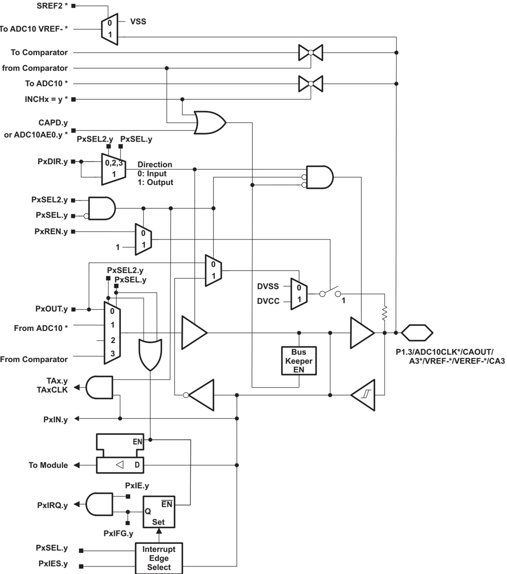
- Note: MSP430G2x53 devices only. MSP430G2x13 devices have no ADC10.
44 Submit Documentation Feedback Copyright © 2011–2013, Texas Instruments Incorporated
Table 17. Port P1 (P1.3) Pin Functions
| PIN NAME (P1.x) | x | FUNCTION | CONTROL BITS AND SIGNALS(1) | ||||
|---|---|---|---|---|---|---|---|
| P1DIR.x | P1SEL.x | P1SEL2.x | ADC10AE.x INCH.x=1(2) | CAPD.y | |||
| P1.3/ ADC10CLK(2)/ CAOUT/ A3(2)/ VREF-(2)/ VEREF-(2)/ CA3/ Pin Osc | 3 | P1.x (I/O) | I: 0; O: 1 | 0 | 0 | 0 | 0 |
| ADC10CLK | 1 | 1 | 0 | 0 | 0 | ||
| CAOUT | 1 | 1 | 1 | 0 | 0 | ||
| A3 | X | X | X | 1 (y = 3) | 0 | ||
| VREF- | X | X | X | 1 | 0 | ||
| VEREF- | X | X | X | 1 | 0 | ||
| CA3 | X | X | X | 0 | 1 (y = 3) | ||
| Capacitive sensing | X | 0 | 1 | 0 | 0 |
(1) X = don't care
(2) MSP430G2x53 devices only
SLAS735J–APRIL 2011–REVISED MAY 2013
Port P1 Pin Schematic: P1.4, Input/Output With Schmitt Trigger
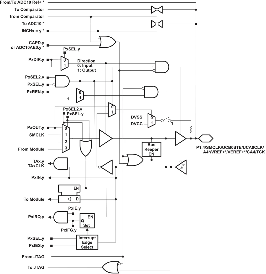
- Note: MSP430G2x52 devices only. MSP430G2x12 devices have no ADC10.
46 Submit Documentation Feedback Copyright © 2011–2013, Texas Instruments Incorporated
Table 18. Port P1 (P1.4) Pin Functions
| PIN NAME (P1.x) | x | FUNCTION | CONTROL BITS AND SIGNALS(1) | |||||
|---|---|---|---|---|---|---|---|---|
| P1DIR.x | P1SEL.x | P1SEL2.x | ADC10AE.x INCH.x=1(2) | JTAG Mode | CAPD.y | |||
| P1.4/ SMCLK/ UCB0STE/ UCA0CLK/ VREF+(2)/ VEREF+(2)/ A4(2)/ CA4 TCK/ Pin Osc | 4 | P1.x (I/O) | I: 0; O: 1 | 0 | 0 | 0 | 0 | 0 |
| SMCLK | 1 | 1 | 0 | 0 | 0 | 0 | ||
| UCB0STE | from USCI | 1 | 1 | 0 | 0 | 0 | ||
| UCA0CLK | from USCI | 1 | 1 | 0 | 0 | 0 | ||
| VREF+ | X | X | X | 1 | 0 | 0 | ||
| VEREF+ | X | X | X | 1 | 0 | 0 | ||
| A4 | X | X | X | 1 (y = 4) | 0 | 0 | ||
| CA4 | X | X | X | 0 | 0 | 1 (y = 4) | ||
| TCK | X | X | X | 0 | 1 | 0 | ||
| Capacitive sensing | X | 0 | 1 | 0 | 0 | 0 |
(1) X = don't care
(2) MSP430G2x53 devices only
SLAS735J–APRIL 2011–REVISED MAY 2013
Port P1 Pin Schematic: P1.5 to P1.7, Input/Output With Schmitt Trigger
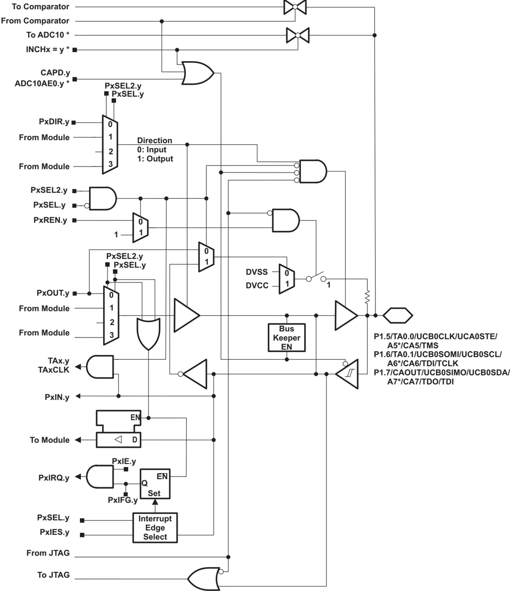
- Note: MSP430G2x53 devices only. MSP430G2x13 devices have no ADC10.
48 Submit Documentation Feedback Copyright © 2011–2013, Texas Instruments Incorporated
Table 19. Port P1 (P1.5 to P1.7) Pin Functions
| PIN NAME (P1.x) | x | FUNCTION | CONTROL BITS AND SIGNALS⁽¹⁾ | |||||
|---|---|---|---|---|---|---|---|---|
| P1DIR.x | P1SEL.x | P1SEL2.x | ADC10AE.x INCH.x=1⁽²⁾ | JTAG Mode | CAPD.y | |||
| P1.5/ TA0.0/ UCB0CLK/ UCA0STE/ A5⁽²⁾/ CA5 TMS Pin Osc | 5 | P1.x (I/O) | I: 0; O: 1 | 0 | 0 | 0 | 0 | 0 |
| TA0.0 | 1 | 1 | 0 | 0 | 0 | 0 | ||
| UCB0CLK | from USCI | 1 | 1 | 0 | 0 | 0 | ||
| UCA0STE | from USCI | 1 | 1 | 0 | 0 | 0 | ||
| A5 | X | X | X | 1 (y = 5) | 0 | 0 | ||
| CA5 | X | X | X | 0 | 0 | 1 (y = 5) | ||
| TMS | X | X | X | 0 | 1 | 0 | ||
| Capacitive sensing | X | 0 | 1 | 0 | 0 | 0 | ||
| P1.6/ TA0.1/ UCB0SOMI/ UCB0SCL/ A6⁽²⁾/ CA6 TDI/TCLK/ Pin Osc | 6 | P1.x (I/O) | I: 0; O: 1 | 0 | 0 | 0 | 0 | 0 |
| TA0.1 | 1 | 1 | 0 | 0 | 0 | 0 | ||
| UCB0SOMI | from USCI | 1 | 1 | 0 | 0 | 0 | ||
| UCB0SCL | from USCI | 1 | 1 | 0 | 0 | 0 | ||
| A6 | X | X | X | 1 (y = 6) | 0 | 0 | ||
| CA6 | X | X | X | 0 | 0 | 1 (y = 6) | ||
| TDI/TCLK | X | X | X | 0 | 1 | 0 | ||
| Capacitive sensing | X | 0 | 1 | 0 | 0 | 0 | ||
| P1.7/ UCB0SIMO/ UCB0SDA/ A7⁽²⁾/ CA7 CAOUT TDO/TDI/ Pin Osc | 7 | P1.x (I/O) | I: 0; O: 1 | 0 | 0 | 0 | 0 | 0 |
| UCB0SIMO | from USCI | 1 | 1 | 0 | 0 | 0 | ||
| UCB0SDA | from USCI | 1 | 1 | 0 | 0 | 0 | ||
| A7 | X | X | X | 1 (y = 7) | 0 | 0 | ||
| CA7 | X | X | X | 0 | 0 | 1 (y = 7) | ||
| CAOUT | 1 | 1 | 0 | 0 | 0 | 0 | ||
| TDO/TDI | X | X | X | 0 | 1 | 0 | ||
| Capacitive sensing | X | 0 | 1 | 0 | 0 | 0 |
(1) X = don't care
(2) MSP430G2x53 devices only
SLAS735J–APRIL 2011–REVISED MAY 2013
Port P2 Pin Schematic: P2.0 to P2.5, Input/Output With Schmitt Trigger
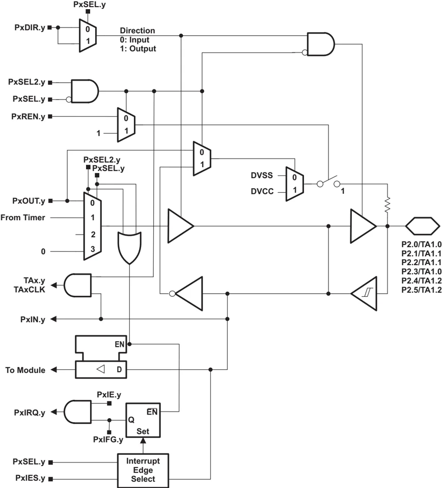
50 Submit Documentation Feedback Copyright © 2011–2013, Texas Instruments Incorporated
Table 20. Port P2 (P2.0 to P2.5) Pin Functions
| PIN NAME (P2.x) | x | FUNCTION | CONTROL BITS AND SIGNALS⁽¹⁾ | ||
|---|---|---|---|---|---|
| P2DIR.x | P2SEL.x | P2SEL2.x | |||
| P2.0/ TA1.0/ Pin Osc | 0 | P2.x (I/O) | I: 0; O: 1 | 0 | 0 |
| Timer1_A3.CCI0A | 0 | 1 | 0 | ||
| Timer1_A3.TA0 | 1 | 1 | 0 | ||
| Capacitive sensing | X | 0 | 1 | ||
| P2.1/ TA1.1/ Pin Osc | 1 | P2.x (I/O) | I: 0; O: 1 | 0 | 0 |
| Timer1_A3.CCI1A | 0 | 1 | 0 | ||
| Timer1_A3.TA1 | 1 | 1 | 0 | ||
| Capacitive sensing | X | 0 | 1 | ||
| P2.2/ TA1.1/ Pin Osc | 2 | P2.x (I/O) | I: 0; O: 1 | 0 | 0 |
| Timer1_A3.CCI1B | 0 | 1 | 0 | ||
| Timer1_A3.TA1 | 1 | 1 | 0 | ||
| Capacitive sensing | X | 0 | 1 | ||
| P2.3/ TA1.0/ Pin Osc | 3 | P2.x (I/O) | I: 0; O: 1 | 0 | 0 |
| Timer1_A3.CCI0B | 0 | 1 | 0 | ||
| Timer1_A3.TA0 | 1 | 1 | 0 | ||
| Capacitive sensing | X | 0 | 1 | ||
| P2.4/ TA1.2/ Pin Osc | 4 | P2.x (I/O) | I: 0; O: 1 | 0 | 0 |
| Timer1_A3.CCI2A | 0 | 1 | 0 | ||
| Timer1_A3.TA2 | 1 | 1 | 0 | ||
| Capacitive sensing | X | 0 | 1 | ||
| P2.5/ TA1.2/ Pin Osc | 5 | P2.x (I/O) | I: 0; O: 1 | 0 | 0 |
| Timer1_A3.CCI2B | 0 | 1 | 0 | ||
| Timer1_A3.TA2 | 1 | 1 | 0 | ||
| Capacitive sensing | X | 0 | 1 |
(1) X = don't care
TEXAS INSTRUMENTS
SLAS735J–APRIL 2011–REVISED MAY 2013 www.ti.com
Port P2 Pin Schematic: P2.6, Input/Output With Schmitt Trigger
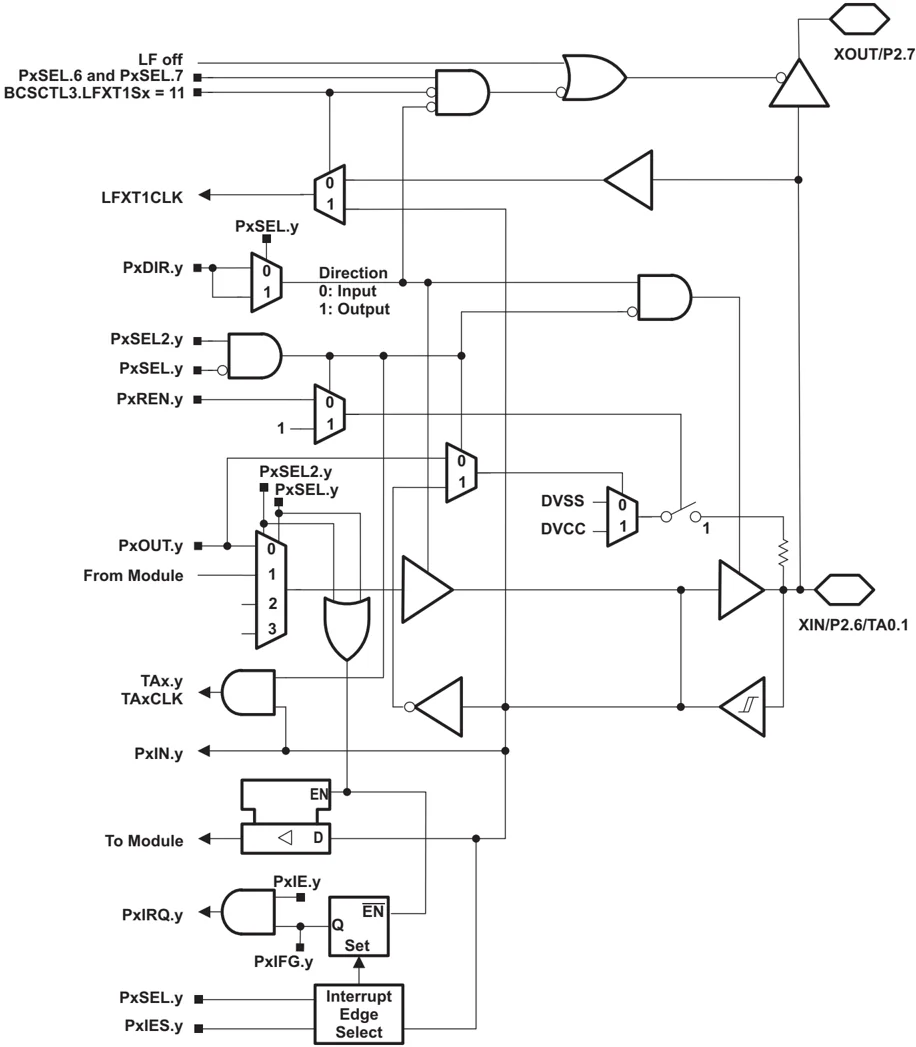
LF off PxSEL.6 and PxSEL.7 BCSCTL3.LFXT1Sx = 11
XOUT/P2.7
LFXT1CLK
PxSEL.y
PxDIR.y
Direction 0: Input 1: Output
PxSEL2.y PxSEL.y PxREN.y
PxSEL2.y PxSEL.y
DVSS DVCC
PxOUT.y From Module
TAx.y TAxCLK
PxIN.y
To Module
PxIE.y PxIRQ.y
PxIFG.y
Interrupt Edge Select
PxSEL.y PxIES.y
XIN/P2.6/TA0.1
52 Submit Documentation Feedback Copyright © 2011–2013, Texas Instruments Incorporated
Table 21. Port P2 (P2.6) Pin Functions
| PIN NAME (P2.x) | x | FUNCTION | CONTROL BITS AND SIGNALS(1) | ||
|---|---|---|---|---|---|
| P2DIR.x | P2SEL.6P2SEL.7 | P2SEL2.6P2SEL2.7 | |||
| XIN | XIN | 0 | 11 | 00 | |
| P2.6 | 6 | P2.x (I/O) | I: 0; O: 1 | 0X | 00 |
| TA0.1 | Timer0_A3.TA1 | 1 | 10 | 00 | |
| Pin Osc | Capacitive sensing | X | 0X | 1X |
(1) X = don't care
SLAS735J–APRIL 2011–REVISED MAY 2013
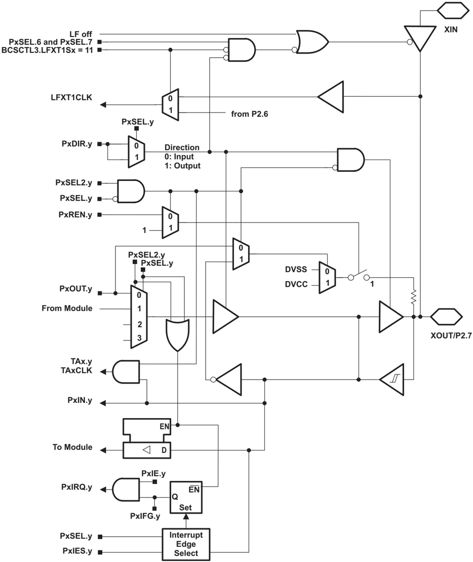
Port P2 Pin Schematic: P2.7, Input/Output With Schmitt Trigger
54 Submit Documentation Feedback
Copyright © 2011–2013, Texas Instruments Incorporated
SLAS735J – APRIL 2011 – REVISED MAY 2013
Table 22. Port P2 (P2.7) Pin Functions
| PIN NAME (P2.x) | x | FUNCTION | CONTROL BITS AND SIGNALS(1) | ||
|---|---|---|---|---|---|
| P2DIR.x | P2SEL.6P2SEL.7 | P2SEL2.6P2SEL2.7 | |||
| XOUT/ | XOUT | 1 | 11 | 00 | |
| P2.7/ | 7 | P2.x (I/O) | I: 0; O: 1 | 0X | 00 |
| Pin Osc | Capacitive sensing | X | 0X | 1X |
(1) X = don't care
Copyright © 2011–2013, Texas Instruments Incorporated Submit Documentation Feedback 55
SLAS735J – APRIL 2011 – REVISED MAY 2013
Port P3 Pin Schematic: P3.0 to P3.7, Input/Output With Schmitt Trigger (28-Pin PW and 32-Pin RHB Packages Only)

56 Submit Documentation Feedback Copyright © 2011–2013, Texas Instruments Incorporated
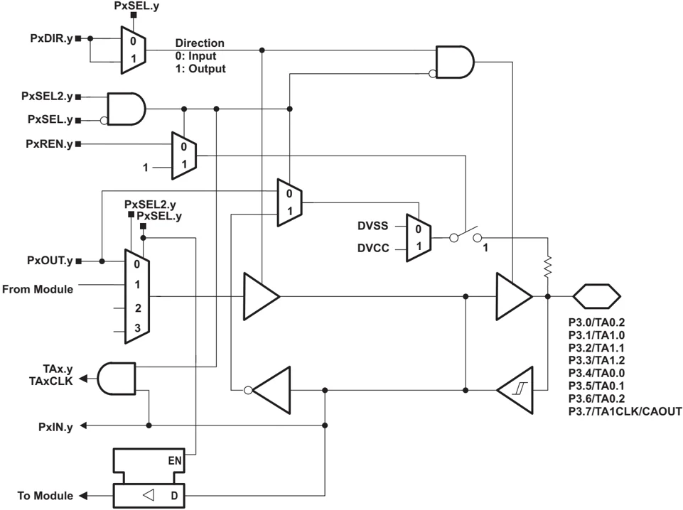
Table 23. Port P3 (P3.0 to P3.7) Pin Functions (28-Pin PW and 32-Pin RHB Packages Only)
| PIN NAME (P3.x) | x | FUNCTION | CONTROL BITS AND SIGNALS(1) | ||
|---|---|---|---|---|---|
| P3DIR.x | P3SEL.x | P3SEL2.x | |||
| P3.0/ TA0.2/ Pin Osc | 0 | P3.x (I/O) | I: 0; O: 1 | 0 | 0 |
| Timer0_A3.CCI2A | 0 | 1 | 0 | ||
| Timer0_A3.TA2 | 1 | 1 | 0 | ||
| Capacitive sensing | X | 0 | 1 | ||
| P3.1/ TA1.0/ Pin Osc | 1 | P3.x (I/O) | I: 0; O: 1 | 0 | 0 |
| Timer1_A3.TA0 | 1 | 1 | 0 | ||
| Capacitive sensing | X | 0 | 1 | ||
| P3.2/ TA1.1/ Pin Osc | 2 | P3.x (I/O) | I: 0; O: 1 | 0 | 0 |
| Timer1_A3.TA1 | 1 | 1 | 0 | ||
| Capacitive sensing | X | 0 | 1 | ||
| P3.3/ TA1.2/ Pin Osc | 3 | P3.x (I/O) | I: 0; O: 1 | 0 | 0 |
| Timer1_A3.TA2 | 1 | 1 | 0 | ||
| Capacitive sensing | X | 0 | 1 | ||
| P3.4/ TA0.0/ Pin Osc | 4 | P3.x (I/O) | I: 0; O: 1 | 0 | 0 |
| Timer0_A3.TA0 | 1 | 1 | 0 | ||
| Capacitive sensing | X | 0 | 1 | ||
| P3.5/ TA0.1/ Pin Osc | 5 | P3.x (I/O) | I: 0; O: 1 | 0 | 0 |
| Timer0_A3.TA1 | 1 | 1 | 0 | ||
| Capacitive sensing | X | 0 | 1 | ||
| P3.6/ TA0.2/ Pin Osc | 6 | P3.x (I/O) | I: 0; O: 1 | 0 | 0 |
| Timer0_A3.TA2 | 1 | 1 | 0 | ||
| Capacitive sensing | X | 0 | 1 | ||
| P3.7/ TA1CLK/ CAOUT/ Pin Osc | 7 | P3.x (I/O) | I: 0; O: 1 | 0 | 0 |
| Timer1_A3.TACLK | 0 | 1 | 0 | ||
| Comparator output | 1 | 1 | 0 | ||
| Capacitive sensing | X | 0 | 1 |
(1) X = don't care
SLAS735J–APRIL 2011–REVISED MAY 2013
REVISION HISTORY
| REVISION | DESCRIPTION |
|---|---|
| SLAS735 | Initial release |
| SLAS735A | Changed Control Bits / Signals column in Table 18Changed Pin Name and Function columns in Table 23 |
| SLAS735B | Changed Storage temperature range limit in Absolute Maximum RatingsAdded BSL functions to P1.1 and P1.5 in Table 2.Added CAOUT information to Table 17. |
| SLAS735C | Changed Tstg, Programmed device, to -55°C to 150°C in Absolute Maximum Ratings.Changed TAG_ADC10_1 value to 0x10 in Table 10. |
| SLAS735D | Added AVCC (RHB package only, pin 29) to Table 2 Terminal Functions.Corrected typo in P3.7/TA1CLK/CAOUT description in Table 2.Corrected PW28 terminal assignment in Input and Output Pin Number columns in Table 13.Changed all port schematics (added buffer after PxOUT.y mux) in Port Schematics. |
| SLAS735E | Table 5 and Table 14, Corrected Timer_A register names. |
| SLAS735F | Added note on TCREF+ in 10-Bit ADC, Built-In Voltage Reference (MSP430G2x53 Only).Corrected signal names on Port P1 Pin Schematic: P1.4, Input/Output With Schmitt Trigger. |
| SLAS735G | Recommended Operating Conditions, Removed mention of USART module from fSYSTEM description.Port P3 Pin Schematic: P3.0 to P3.7, Input/Output With Schmitt Trigger (28-Pin PW and 32-Pin RHB Packages Only),Added PW28 to available packages. |
| SLAS735H | Recommended Operating Conditions, Added test conditions for typical values.Pin-Oscillator Frequency – Ports Px, Corrected resistor value in note (1).POR, BOR, Added note (2). |
| SLAS735I | Throughout, Changed all variations of touch sense(1) to capacitive touch. |
| SLAS735J | Removed all information regarding MSP430G2113. |
(1) TouchSense is a trademark of Immersion Corporation.
58 Submit Documentation Feedback Copyright © 2011–2013, Texas Instruments Incorporated