MIXED SIGNAL MICROCONTROLLER
FEATURES
- Low Supply-Voltage Range: 1.8 V to 3.6 V
- Ultra-Low Power Consumption
- Active Mode: 230 μA at 1 MHz, 2.2 V
- Standby Mode: 0.5 μA
- Off Mode (RAM Retention): 0.1 μA
- Five Power-Saving Modes
- Ultra-Fast Wake-Up From Standby Mode in Less Than 1 μs
- 16-Bit RISC Architecture, 62.5-ns Instruction Cycle Time
- Basic Clock Module Configurations
- Internal Frequencies up to 16 MHz With Four Calibrated Frequency
- Internal Very-Low-Power Low-Frequency (LF) Oscillator
- 32-kHz Crystal
- External Digital Clock Source
- Two 16-Bit Timer_A With Three Capture/Compare Registers
- Up to 24 Capacitive-Touch Enabled I/O Pins
- Universal Serial Communication Interface (USCI)
- Enhanced UART Supporting Auto Baudrate Detection (LIN)
- IrDA Encoder and Decoder
- Synchronous SPI
- I²C™
- On-Chip Comparator for Analog Signal Compare Function or Slope Analog-to-Digital (A/D) Conversion
- 10-Bit 200-ksps Analog-to-Digital (A/D) Converter With Internal Reference, Sample-and-Hold, and Autoscan (See Table 1)
- Brownout Detector
- Serial Onboard Programming, No External Programming Voltage Needed, Programmable Code Protection by Security Fuse
- On-Chip Emulation Logic With Spy-Bi-Wire Interface
- Family Members are Summarized in Table 1
- Package Options
- TSSOP: 20 Pin, 28 Pin
- PDIP: 20 Pin
- QFN: 32 Pin
- For Complete Module Descriptions, See the MSP430x2xx Family User’s Guide (SLAU144)
DESCRIPTION
The Texas Instruments MSP430 family of ultra-low-power microcontrollers consists of several devices featuring different sets of peripherals targeted for various applications. The architecture, combined with five low-power modes, is optimized to achieve extended battery life in portable measurement applications. The device features a powerful 16-bit RISC CPU, 16-bit registers, and constant generators that contribute to maximum code efficiency. The digitally controlled oscillator (DCO) allows wake-up from low-power modes to active mode in less than 1 μs.
The MSP430G2x13 and MSP430G2x53 series are ultra-low-power mixed signal microcontrollers with built-in 16-bit timers, up to 24 I/O capacitive-touch enabled pins, a versatile analog comparator, and built-in communication capability using the universal serial communication interface. In addition the MSP430G2x53 family members have a 10-bit analog-to-digital (A/D) converter. For configuration details see Table 1.
Typical applications include low-cost sensor systems that capture analog signals, convert them to digital values, and then process the data for display or for transmission to a host system.
Please be aware that an important notice concerning availability, standard warranty, and use in critical applications of Texas Instruments semiconductor products and disclaimers thereto appears at the end of this data sheet.
PRODUCTION DATA information is current as of publication date. Products conform to specifications per the terms of the Texas Instruments standard warranty. Production processing does not necessarily include testing of all parameters.
Copyright © 2011–2013, Texas Instruments Incorporated

SLAS735J – APRIL 2011 – REVISED MAY 2013
Table 1. Available Options (1)(2)
| Device | BSL | EEM | Flash (KB) | RAM (B) | Timer_A | COMP_A+ Channel | ADC10 Channel | USCI_A0, USCI_B0 | Clock | I/O | Package Type |
|---|---|---|---|---|---|---|---|---|---|---|---|
| MSP430G2553IRHB32 | 1 | 1 | 16 | 512 | 2x TA3 | 8 | 8 | 1 | LF, DCO, VLO | 24 | 32-QFN |
| MSP430G2553IPW28 | 1 | 1 | 16 | 512 | 2x TA3 | 8 | 8 | 1 | LF, DCO, VLO | 24 | 28-TSSOP |
| MSP430G2553IPW20 | 1 | 1 | 16 | 512 | 2x TA3 | 8 | 8 | 1 | LF, DCO, VLO | 16 | 20-TSSOP |
| MSP430G2553IN20 | 1 | 1 | 16 | 512 | 2x TA3 | 8 | 8 | 1 | LF, DCO, VLO | 16 | 20-PDIP |
| MSP430G2453IRHB32 | 1 | 1 | 8 | 512 | 2x TA3 | 8 | 8 | 1 | LF, DCO, VLO | 24 | 32-QFN |
| MSP430G2453IPW28 | 1 | 1 | 8 | 512 | 2x TA3 | 8 | 8 | 1 | LF, DCO, VLO | 24 | 28-TSSOP |
| MSP430G2453IPW20 | 1 | 1 | 8 | 512 | 2x TA3 | 8 | 8 | 1 | LF, DCO, VLO | 16 | 20-TSSOP |
| MSP430G2453IN20 | 1 | 1 | 8 | 512 | 2x TA3 | 8 | 8 | 1 | LF, DCO, VLO | 16 | 20-PDIP |
| MSP430G2353IRHB32 | 1 | 1 | 4 | 256 | 2x TA3 | 8 | 8 | 1 | LF, DCO, VLO | 24 | 32-QFN |
| MSP430G2353IPW28 | 1 | 1 | 4 | 256 | 2x TA3 | 8 | 8 | 1 | LF, DCO, VLO | 24 | 28-TSSOP |
| MSP430G2353IPW20 | 1 | 1 | 4 | 256 | 2x TA3 | 8 | 8 | 1 | LF, DCO, VLO | 16 | 20-TSSOP |
| MSP430G2353IN20 | 1 | 1 | 4 | 256 | 2x TA3 | 8 | 8 | 1 | LF, DCO, VLO | 16 | 20-PDIP |
| MSP430G2253IRHB32 | 1 | 1 | 2 | 256 | 2x TA3 | 8 | 8 | 1 | LF, DCO, VLO | 24 | 32-QFN |
| MSP430G2253IPW28 | 1 | 1 | 2 | 256 | 2x TA3 | 8 | 8 | 1 | LF, DCO, VLO | 24 | 28-TSSOP |
| MSP430G2253IPW20 | 1 | 1 | 2 | 256 | 2x TA3 | 8 | 8 | 1 | LF, DCO, VLO | 16 | 20-TSSOP |
| MSP430G2253IN20 | 1 | 1 | 2 | 256 | 2x TA3 | 8 | 8 | 1 | LF, DCO, VLO | 16 | 20-PDIP |
| MSP430G2153IRHB32 | 1 | 1 | 1 | 256 | 2x TA3 | 8 | 8 | 1 | LF, DCO, VLO | 24 | 32-QFN |
| MSP430G2153IPW28 | 1 | 1 | 1 | 256 | 2x TA3 | 8 | 8 | 1 | LF, DCO, VLO | 24 | 28-TSSOP |
| MSP430G2153IPW20 | 1 | 1 | 1 | 256 | 2x TA3 | 8 | 8 | 1 | LF, DCO, VLO | 16 | 20-TSSOP |
| MSP430G2153IN20 | 1 | 1 | 1 | 256 | 2x TA3 | 8 | 8 | 1 | LF, DCO, VLO | 16 | 20-PDIP |
| MSP430G2513IRHB32 | 1 | 1 | 16 | 512 | 2x TA3 | 8 | - | 1 | LF, DCO, VLO | 24 | 32-QFN |
| MSP430G2513IPW28 | 1 | 1 | 16 | 512 | 2x TA3 | 8 | - | 1 | LF, DCO, VLO | 24 | 28-TSSOP |
| MSP430G2513IPW20 | 1 | 1 | 16 | 512 | 2x TA3 | 8 | - | 1 | LF, DCO, VLO | 16 | 20-TSSOP |
| MSP430G2513IN20 | 1 | 1 | 16 | 512 | 2x TA3 | 8 | - | 1 | LF, DCO, VLO | 16 | 20-PDIP |
| MSP430G2413IRHB32 | 1 | 1 | 8 | 512 | 2x TA3 | 8 | - | 1 | LF, DCO, VLO | 24 | 32-QFN |
| MSP430G2413IPW28 | 1 | 1 | 8 | 512 | 2x TA3 | 8 | - | 1 | LF, DCO, VLO | 24 | 28-TSSOP |
| MSP430G2413IPW20 | 1 | 1 | 8 | 512 | 2x TA3 | 8 | - | 1 | LF, DCO, VLO | 16 | 20-TSSOP |
| MSP430G2413IN20 | 1 | 1 | 8 | 512 | 2x TA3 | 8 | - | 1 | LF, DCO, VLO | 16 | 20-PDIP |
| MSP430G2313IRHB32 | 1 | 1 | 4 | 256 | 2x TA3 | 8 | - | 1 | LF, DCO, VLO | 24 | 32-QFN |
| MSP430G2313IPW28 | 1 | 1 | 4 | 256 | 2x TA3 | 8 | - | 1 | LF, DCO, VLO | 24 | 28-TSSOP |
| MSP430G2313IPW20 | 1 | 1 | 4 | 256 | 2x TA3 | 8 | - | 1 | LF, DCO, VLO | 16 | 20-TSSOP |
| MSP430G2313IN20 | 1 | 1 | 4 | 256 | 2x TA3 | 8 | - | 1 | LF, DCO, VLO | 16 | 20-PDIP |
| MSP430G2213IRHB32 | 1 | 1 | 2 | 256 | 2x TA3 | 8 | - | 1 | LF, DCO, VLO | 24 | 32-QFN |
| MSP430G2213IPW28 | 1 | 1 | 2 | 256 | 2x TA3 | 8 | - | 1 | LF, DCO, VLO | 24 | 28-TSSOP |
| MSP430G2213IPW20 | 1 | 1 | 2 | 256 | 2x TA3 | 8 | - | 1 | LF, DCO, VLO | 16 | 20-TSSOP |
| MSP430G2213IN20 | 1 | 1 | 2 | 256 | 2x TA3 | 8 | - | 1 | LF, DCO, VLO | 16 | 20-PDIP |
(1) For the most current package and ordering information, see the Package Option Addendum at the end of this document, or see the TI web site at www.ti.com.
(2) Package drawings, thermal data, and symbolization are available at www.ti.com/packaging.
2 Submit Documentation Feedback Copyright © 2011–2013, Texas Instruments Incorporated
MSP430G2x53
MSP430G2x13
www.ti.com SLAS735J–APRIL 2011–REVISED MAY 2013
Device Pinout, MSP430G2x13 and MSP430G2x53, 20-Pin Devices, TSSOP and PDIP
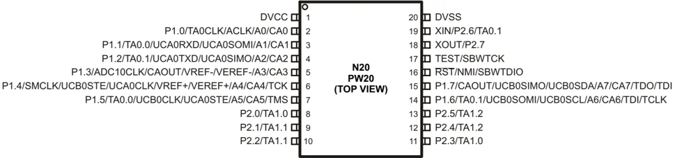
NOTE: ADC10 is available on MSP430G2x53 devices only. NOTE: The pulldown resistors of port P3 should be enabled by setting P3REN.x = 1.
Device Pinout, MSP430G2x13 and MSP430G2x53, 28-Pin Devices, TSSOP
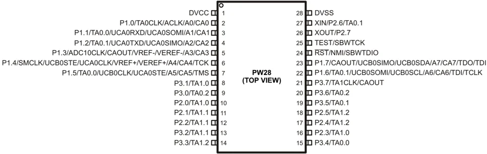
NOTE: ADC10 is available on MSP430G2x53 devices only.
Copyright © 2011–2013, Texas Instruments Incorporated Submit Documentation Feedback 3
SLAS735J–APRIL 2011–REVISED MAY 2013
Device Pinout, MSP430G2x13 and MSP430G2x53, 32-Pin Devices, QFN
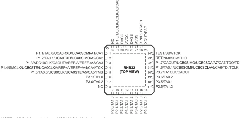
NOTE: ADC10 is available on MSP430G2x53 devices only.
4 Submit Documentation Feedback
Copyright © 2011–2013, Texas Instruments Incorporated
www.ti.com SLAS735J–APRIL 2011–REVISED MAY 2013
Functional Block Diagram, MSP430G2x53
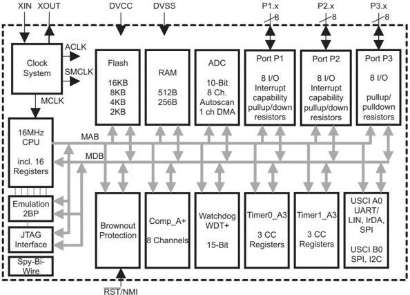
NOTE: Port P3 is available on 28-pin and 32-pin devices only.
Functional Block Diagram, MSP430G2x13
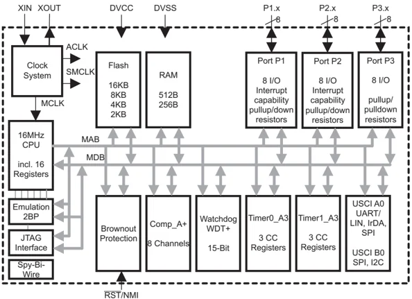
NOTE: Port P3 is available on 28-pin and 32-pin devices only.
Copyright © 2011–2013, Texas Instruments Incorporated Submit Documentation Feedback 5
SLAS735J – APRIL 2011 – REVISED MAY 2013
Table 2. Terminal Functions
| TERMINAL | I/O | DESCRIPTION | |||
|---|---|---|---|---|---|
| NAME | NO. | ||||
| PW20, N20 | PW28 | RHB32 | |||
| P1.0/ TA0CLK/ ACLK/ A0 CA0 | 2 | 2 | 31 | I/O | General-purpose digital I/O pinTimer0_A, clock signal TACLK inputACLK signal outputADC10 analog input A0(1)Comparator_A+, CA0 input |
| P1.1/ TA0.0/ UCA0RXD/ UCA0SOMI/ A1/ CA1 | 3 | 3 | 1 | I/O | General-purpose digital I/O pinTimer0_A, capture: CCI0A input, compare: Out0 output / BSL transmitUSCI_A0 UART mode: receive data inputUSCI_A0 SPI mode: slave data out/master inADC10 analog input A1(1)Comparator_A+, CA1 input |
| P1.2/ TA0.1/ UCA0TXD/ UCA0SIMO/ A2/ CA2 | 4 | 4 | 2 | I/O | General-purpose digital I/O pinTimer0_A, capture: CCI1A input, compare: Out1 outputUSCI_A0 UART mode: transmit data outputUSCI_A0 SPI mode: slave data in/master outADC10 analog input A2(1)Comparator_A+, CA2 input |
| P1.3/ ADC10CLK/ A3/ VREF-/VEREF-/ CA3/ CAOUT | 5 | 5 | 3 | I/O | General-purpose digital I/O pinADC10, conversion clock output(1)ADC10 analog input A3(1)ADC10 negative reference voltage (1)Comparator_A+, CA3 inputComparator_A+, output |
| P1.4/ SMCLK/ UCB0STE/ UCA0CLK/ A4/ VREF+/VEREF+/ CA4/ TCK | 6 | 6 | 4 | I/O | General-purpose digital I/O pinSMCLK signal outputUSCI_B0 slave transmit enableUSCI_A0 clock input/outputADC10 analog input A4(1)ADC10 positive reference voltage(1)Comparator_A+, CA4 inputJTAG test clock, input terminal for device programming and test |
| P1.5/ TA0.0/ UCB0CLK/ UCA0STE/ A5/ CA5/ TMS | 7 | 7 | 5 | I/O | General-purpose digital I/O pinTimer0_A, compare: Out0 output / BSL receiveUSCI_B0 clock input/outputUSCI_A0 slave transmit enableADC10 analog input A5(1)Comparator_A+, CA5 inputJTAG test mode select, input terminal for device programming and test |
(1) MSP430G2x53 devices only
6 Submit Documentation Feedback
Copyright © 2011–2013, Texas Instruments Incorporated
Table 2. Terminal Functions (continued)
| NAME | TERMINAL | I/O | DESCRIPTION | ||
|---|---|---|---|---|---|
| NO. | |||||
| PW20, N20 | PW28 | RHB32 | |||
| P1.6/ TA0.1/ A6/ CA6/ UCB0SOMI/ UCB0SCL/ TDI/TCLK | 14 | 22 | 21 | I/O | General-purpose digital I/O pinTimer0_A, compare: Out1 outputADC10 analog input A6(1)Comparator_A+, CA6 inputUSCI_B0 SPI mode: slave out master inUSCI_B0 I2C mode: SCL I2C clockJTAG test data input or test clock input during programming and test |
| P1.7/ A7/ CA7/ CAOUT/ UCB0SIMO/ UCB0SDA/ TDO/TDI | 15 | 23 | 22 | I/O | General-purpose digital I/O pinADC10 analog input A7(1)Comparator_A+, CA7 inputComparator_A+, outputUSCI_B0 SPI mode: slave in master outUSCI_B0 I2C mode: SDA I2C dataJTAG test data output terminal or test data input during programming and test(2) |
| P2.0/ TA1.0 | 8 | 10 | 9 | I/O | General-purpose digital I/O pinTimer1_A, capture: CCI0A input, compare: Out0 output |
| P2.1/ TA1.1 | 9 | 11 | 10 | I/O | General-purpose digital I/O pinTimer1_A, capture: CCI1A input, compare: Out1 output |
| P2.2/ TA1.1 | 10 | 12 | 11 | I/O | General-purpose digital I/O pinTimer1_A, capture: CCI1B input, compare: Out1 output |
| P2.3/ TA1.0 | 11 | 16 | 15 | I/O | General-purpose digital I/O pinTimer1_A, capture: CCI0B input, compare: Out0 output |
| P2.4/ TA1.2 | 12 | 17 | 16 | I/O | General-purpose digital I/O pinTimer1_A, capture: CCI2A input, compare: Out2 output |
| P2.5/ TA1.2 | 13 | 18 | 17 | I/O | General-purpose digital I/O pinTimer1_A, capture: CCI2B input, compare: Out2 output |
| XIN/ P2.6/ TA0.1 | 19 | 27 | 26 | I/O | Input terminal of crystal oscillatorGeneral-purpose digital I/O pinTimer0_A, compare: Out1 output |
| XOUT/ P2.7 | 18 | 26 | 25 | I/O | Output terminal of crystal oscillator(3)General-purpose digital I/O pin |
| P3.0/ TA0.2 | - | 9 | 7 | I/O | General-purpose digital I/O pinTimer0_A, capture: CCI2A input, compare: Out2 output |
| P3.1/ TA1.0 | - | 8 | 6 | I/O | General-purpose digital I/O pinTimer1_A, compare: Out0 output |
| P3.2/ TA1.1 | - | 13 | 12 | I/O | General-purpose digital I/O pinTimer1_A, compare: Out1 output |
| P3.3/ TA1.2 | - | 14 | 13 | I/O | General-purpose digital I/OTimer1_A, compare: Out2 output |
| P3.4/ TA0.0 | - | 15 | 14 | I/O | General-purpose digital I/OTimer0_A, compare: Out0 output |
(2) TDO or TDI is selected via JTAG instruction.
(3) If XOUT/P2.7 is used as an input, excess current flows until P2SEL.7 is cleared. This is due to the oscillator output driver connection to this pad after reset.
SLAS735J – APRIL 2011 – REVISED MAY 2013
Table 2. Terminal Functions (continued)
| NAME | TERMINAL | I/O | DESCRIPTION | ||
|---|---|---|---|---|---|
| NO. | |||||
| PW20, N20 | PW28 | RHB32 | |||
| P3.5/TA0.1 | - | 19 | 18 | I/O | General-purpose digital I/OTimer0_A, compare: Out1 output |
| P3.6/TA0.2 | - | 20 | 19 | I/O | General-purpose digital I/OTimer0_A, compare: Out2 output |
| P3.7/TA1CLK/CAOUT | - | 21 | 20 | I/O | General-purpose digital I/OTimer1_A, clock signal TACLK inputComparator_A+, output |
| RST/NMI/SBWTDIO | 16 | 24 | 23 | I | ResetNonmaskable interrupt inputSpy-Bi-Wire test data input/output during programming and test |
| TEST/SBW TCK | 17 | 25 | 24 | I | Selects test mode for JTAG pins on Port 1. The device protection fuse is connected to TEST.Spy-Bi-Wire test clock input during programming and test |
| AVCC | NA | NA | 29 | NA | Analog supply voltage |
| DVCC | 1 | 1 | 30 | NA | Digital supply voltage |
| DVSS | 20 | 28 | 27, 28 | NA | Ground reference |
| NC | NA | NA | 8, 32 | NA | Not connected |
| QFN Pad | NA | NA | Pad | NA | QFN package pad. Connection to VSS is recommended. |
8 Submit Documentation Feedback Copyright © 2011–2013, Texas Instruments Incorporated
SHORT-FORM DESCRIPTION
CPU
The MSP430 CPU has a 16-bit RISC architecture that is highly transparent to the application. All operations, other than program-flow instructions, are performed as register operations in conjunction with seven addressing modes for source operand and four addressing modes for destination operand.
The CPU is integrated with 16 registers that provide reduced instruction execution time. The register-to-register operation execution time is one cycle of the CPU clock.
Four of the registers, R0 to R3, are dedicated as program counter, stack pointer, status register, and constant generator, respectively. The remaining registers are general-purpose registers.
Peripherals are connected to the CPU using data, address, and control buses, and can be handled with all instructions.
The instruction set consists of the original 51 instructions with three formats and seven address modes and additional instructions for the expanded address range. Each instruction can operate on word and byte data.
Instruction Set
The instruction set consists of 51 instructions with three formats and seven address modes. Each instruction can operate on word and byte data. Table 3 shows examples of the three types of instruction formats; Table 4 shows the address modes.
Table 3. Instruction Word Formats
| INSTRUCTION FORMAT | EXAMPLE | OPERATION |
|---|---|---|
| Dual operands, source-destination | ADD R4,R5 | R4 + R5 ---> R5 |
| Single operands, destination only | CALL R8 | PC --->(TOS), R8---> PC |
| Relative jump, un/conditional | JNE | Jump-on-equal bit = 0 |
Table 4. Address Mode Descriptions (1)
| ADDRESS MODE | S | D | SYNTAX | EXAMPLE | OPERATION |
|---|---|---|---|---|---|
| Register | ✓ | ✓ | MOV Rs,Rd | MOV R10,R11 | R10 ---> R11 |
| Indexed | ✓ | ✓ | MOV X(Rn),Y(Rm) | MOV 2(R5),6(R6) | M(2+R5) ---> M(6+R6) |
| Symbolic (PC relative) | ✓ | ✓ | MOV EDE,TONI | M(EDE) ---> M(TONI) | |
| Absolute | ✓ | ✓ | MOV &MEM,&TCDAT | M(MEM) ---> M(TCDAT) | |
| Indirect | ✓ | MOV @Rn,Y(Rm) | MOV @R10,Tab(R6) | M(R10) ---> M(Tab+R6) | |
| Indirect autoincrement | ✓ | MOV @Rn+,Rm | MOV @R10+,R11 | M(R10) ---> R11 | |
| R10 + 2---> R10 | |||||
| Immediate | ✓ | MOV #X,TONI | MOV #45,TONI | #45 ---> M(TONI) |
(1) S = source, D = destination
SLAS735J–APRIL 2011–REVISED MAY 2013
Operating Modes
The MSP430 has one active mode and five software selectable low-power modes of operation. An interrupt event can wake up the device from any of the low-power modes, service the request, and restore back to the low-power mode on return from the interrupt program.
The following six operating modes can be configured by software:
- Active mode (AM)
- All clocks are active
- Low-power mode 0 (LPM0)
- CPU is disabled
- ACLK and SMCLK remain active, MCLK is disabled
- Low-power mode 1 (LPM1)
- CPU is disabled
- ACLK and SMCLK remain active, MCLK is disabled
- DCO's dc generator is disabled if DCO not used in active mode
- Low-power mode 2 (LPM2)
- CPU is disabled
- MCLK and SMCLK are disabled
- DCO's dc generator remains enabled
- ACLK remains active
- Low-power mode 3 (LPM3)
- CPU is disabled
- MCLK and SMCLK are disabled
- DCO's dc generator is disabled
- ACLK remains active
- Low-power mode 4 (LPM4)
- CPU is disabled
- ACLK is disabled
- MCLK and SMCLK are disabled
- DCO's dc generator is disabled
- Crystal oscillator is stopped
10 Submit Documentation Feedback Copyright © 2011–2013, Texas Instruments Incorporated
Interrupt Vector Addresses
The interrupt vectors and the power-up starting address are located in the address range 0FFFFh to 0FFC0h. The vector contains the 16-bit address of the appropriate interrupt handler instruction sequence.
If the reset vector (located at address 0FFFEh) contains 0FFFFh (for example, flash is not programmed), the CPU goes into LPM4 immediately after power-up.
Table 5. Interrupt Sources, Flags, and Vectors
| INTERRUPT SOURCE | INTERRUPT FLAG | SYSTEM INTERRUPT | WORD ADDRESS | PRIORITY |
|---|---|---|---|---|
| Power-UpExternal ResetWatchdog Timer+Flash key violationPC out-of-range(1) | PORIFGRSTIFGWDTIFGKEYV(2) | Reset | 0FFFEh | 31, highest |
| NMIOscillator faultFlash memory access violation | NMIIFGOFIFGACCVIFG(2)(3) | (non)-maskable(non)-maskable(non)-maskable | 0FFFC h | 30 |
| Timer1_A3 | TA1CCR0 CCIFG(4) | maskable | 0FFFAh | 29 |
| Timer1_A3 | TA1CCR2 TA1CCR1 CCIFG,TAIFG(2)(4) | maskable | 0FFF8h | 28 |
| Comparator_A+ | CAIFG(4) | maskable | 0FFF6h | 27 |
| Watchdog Timer+ | WDTIFG | maskable | 0FFF4h | 26 |
| Timer0_A3 | TA0CCR0 CCIFG(4) | maskable | 0FFF2h | 25 |
| Timer0_A3 | TA0CCR2 TA0CCR1 CCIFG, TAIFG(5)(4) | maskable | 0FFF0h | 24 |
| USCI_A0/USCI_B0 receiveUSCI_B0 I2C status | UCA0RXIFG, UCB0RXIFG(2)(5) | maskable | 0FFEEh | 23 |
| USCI_A0/USCI_B0 transmitUSCI_B0 I2C receive/transmit | UCA0TXIFG, UCB0TXIFG(2)(6) | maskable | 0FFEC h | 22 |
| ADC10(MSP430G2x53 only) | ADC10IFG(4) | maskable | 0FFEAh | 21 |
| 0FFE8h | 20 | |||
| I/O Port P2 (up to eight flags) | P2IFG.0 to P2IFG.7(2)(4) | maskable | 0FFE6h | 19 |
| I/O Port P1 (up to eight flags) | P1IFG.0 to P1IFG.7(2)(4) | maskable | 0FFE4h | 18 |
| 0FFE2h | 17 | |||
| 0FFE0h | 16 | |||
| See (7) | 0FFDEh | 15 | ||
| See (8) | 0FFDEh to 0FFC0h | 14 to 0, lowest |
(1) A reset is generated if the CPU tries to fetch instructions from within the module register memory address range (0h to 01FFh) or from within unused address ranges.
(2) Multiple source flags
(3) (non)-maskable: the individual interrupt-enable bit can disable an interrupt event, but the general interrupt enable cannot.
(4) Interrupt flags are located in the module.
(5) In SPI mode: UCB0RXIFG. In I2C mode: UCALIFG, UCNACKIFG, ICSTTIFG, UCSTPIFG.
(6) In UART or SPI mode: UCB0TXIFG. In I2C mode: UCB0RXIFG, UCB0TXIFG.
(7) This location is used as bootstrap loader security key (BSLSKEY). A 0xAA55 at this location disables the BSL completely. A zero (0h) disables the erasure of the flash if an invalid password is supplied.
(8) The interrupt vectors at addresses 0FFDEh to 0FFC0h are not used in this device and can be used for regular program code if necessary.
SLAS735J – APRIL 2011 – REVISED MAY 2013
Special Function Registers (SFRs)
Most interrupt and module enable bits are collected into the lowest address space. Special function register bits not allocated to a functional purpose are not physically present in the device. Simple software access is provided with this arrangement.
Legend
- rw: Bit can be read and written.
- rw-0,1: Bit can be read and written. It is reset or set by PUC.
- rw-(0,1): Bit can be read and written. It is reset or set by POR.
- □□□ SFR bit is not present in device.
Table 6. Interrupt Enable Register 1 and 2
| Address | 7 | 6 | 5 | 4 | 3 | 2 | 1 | 0 |
|---|---|---|---|---|---|---|---|---|
| 00h | ACCVIE | NMIIIE | OFIE | WDTIE | ||||
| rw-0 | rw-0 | rw-0 | rw-0 |
- WDTIE: Watchdog Timer interrupt enable. Inactive if watchdog mode is selected. Active if Watchdog Timer is configured in interval timer mode.
- OFIE: Oscillator fault interrupt enable
- NMIIE: (Non)maskable interrupt enable
- ACCVIE: Flash access violation interrupt enable
| Address | 7 | 6 | 5 | 4 | 3 | 2 | 1 | 0 |
|---|---|---|---|---|---|---|---|---|
| 01h | UCB0TXIE | UCB0RXIE | UCA0TXIE | UCA0RXIE | ||||
| rw-0 | rw-0 | rw-0 | rw-0 |
- UCA0RXIE: USCI_A0 receive interrupt enable
- UCA0TXIE: USCI_A0 transmit interrupt enable
- UCB0RXIE: USCI_B0 receive interrupt enable
- UCB0TXIE: USCI_B0 transmit interrupt enable
Table 7. Interrupt Flag Register 1 and 2
| Address | 7 | 6 | 5 | 4 | 3 | 2 | 1 | 0 |
|---|---|---|---|---|---|---|---|---|
| 02h | NMIIFG | RSTIFG | PORIFG | OFIFG | WDTIFG | |||
| rw-0 | rw-(0) | rw-(1) | rw-1 | rw-(0) |
- WDTIFG: Set on watchdog timer overflow (in watchdog mode) or security key violation. Reset on VCC power-on or a reset condition at the RST/NMI pin in reset mode.
- OFIFG: Flag set on oscillator fault.
- PORIFG: Power-On Reset interrupt flag. Set on VCC power-up.
- RSTIFG: External reset interrupt flag. Set on a reset condition at RST/NMI pin in reset mode. Reset on VCC power-up.
- NMIIFG: Set via RST/NMI pin
| Address | 7 | 6 | 5 | 4 | 3 | 2 | 1 | 0 |
|---|---|---|---|---|---|---|---|---|
| 03h | UCB0TXIFG | UCB0RXIFG | UCA0TXIFG | UCA0RXIFG | ||||
| rw-1 | rw-0 | rw-1 | rw-0 |
- UCA0RXIFG: USCI_A0 receive interrupt flag
- UCA0TXIFG: USCI_A0 transmit interrupt flag
- UCB0RXIFG: USCI_B0 receive interrupt flag
- UCB0TXIFG: USCI_B0 transmit interrupt flag
12 Submit Documentation Feedback
Copyright © 2011–2013, Texas Instruments Incorporated




Memory Organization
Table 8. Memory Organization
| Memory | Size | MSP430G2153 | MSP430G2253 MSP430G2213 | MSP430G2353 MSP430G2313 | MSP430G2453 MSP430G2413 | MSP430G2553 MSP430G2513 |
|---|---|---|---|---|---|---|
| Main: interrupt vector | Flash | 1kB 0xFFFF to 0xFFC0 | 2kB 0xFFFF to 0xFFC0 | 4kB 0xFFFF to 0xFFC0 | 8kB 0xFFFF to 0xFFC0 | 16kB 0xFFFF to 0xFFC0 |
| Main: code memory | Flash | 0xFFFF to 0xFC00 | 0xFFFF to 0xF800 | 0xFFFF to 0xF000 | 0xFFFF to 0xE000 | 0xFFFF to 0xC000 |
| Information memory | Size | 256 Byte | 256 Byte | 256 Byte | 256 Byte | 256 Byte |
| Flash | 010FFh to 01000h | 010FFh to 01000h | 010FFh to 01000h | 010FFh to 01000h | 010FFh to 01000h | |
| RAM | Size | 256 Byte 0x02FF to 0x0200 | 256 Byte 0x02FF to 0x0200 | 256 Byte 0x02FF to 0x0200 | 512 Byte 0x03FF to 0x0200 | 512 Byte 0x03FF to 0x0200 |
| Peripherals | 16-bit | 01FFh to 0100h | 01FFh to 0100h | 01FFh to 0100h | 01FFh to 0100h | 01FFh to 0100h |
| 8-bit | 0FFh to 010h | 0FFh to 010h | 0FFh to 010h | 0FFh to 010h | 0FFh to 010h | |
| 8-bit SFR | 0Fh to 00h | 0Fh to 00h | 0Fh to 00h | 0Fh to 00h | 0Fh to 00h |
Bootstrap Loader (BSL)
The MSP430 BSL enables users to program the flash memory or RAM using a UART serial interface. Access to the MSP430 memory via the BSL is protected by user-defined password. For complete description of the features of the BSL and its implementation, see the MSP430 Programming Via the Bootstrap Loader User's Guide (SLAU319).
Table 9. BSL Function Pins
| BSL FUNCTION | 20-PIN PW PACKAGE 20-PIN N PACKAGE | 28-PIN PACKAGE PW | 32-PIN PACKAGE RHB |
|---|---|---|---|
| Data transmit | 3 - P1.1 | 3 - P1.1 | 1 - P1.1 |
| Data receive | 7 - P1.5 | 7 - P1.5 | 5 - P1.5 |
Flash Memory
The flash memory can be programmed via the Spy-Bi-Wire/JTAG port or in-system by the CPU. The CPU can perform single-byte and single-word writes to the flash memory. Features of the flash memory include:
- Flash memory has n segments of main memory and four segments of information memory (A to D) of 64 bytes each. Each segment in main memory is 512 bytes in size.
- Segments 0 to n may be erased in one step, or each segment may be individually erased.
- Segments A to D can be erased individually or as a group with segments 0 to n. Segments A to D are also called information memory.
- Segment A contains calibration data. After reset segment A is protected against programming and erasing. It can be unlocked but care should be taken not to erase this segment if the device-specific calibration data is required.
MSP430G2x53
TEXAS INSTRUMENTS
SLAS735J–APRIL 2011–REVISED MAY 2013
Peripherals
Peripherals are connected to the CPU through data, address, and control buses and can be handled using all instructions. For complete module descriptions, see the MSP430x2xx Family User's Guide (SLAU144).
Oscillator and System Clock
The clock system is supported by the basic clock module that includes support for a 32768-Hz watch crystal oscillator, an internal very-low-power low-frequency oscillator and an internal digitally controlled oscillator (DCO). The basic clock module is designed to meet the requirements of both low system cost and low power consumption. The internal DCO provides a fast turn-on clock source and stabilizes in less than 1 \mus. The basic clock module provides the following clock signals:
- Auxiliary clock (ACLK), sourced either from a 32768-Hz watch crystal or the internal LF oscillator.
- Main clock (MCLK), the system clock used by the CPU.
- Sub-Main clock (SMCLK), the sub-system clock used by the peripheral modules.
The DCO settings to calibrate the DCO output frequency are stored in the information memory segment A.
Main DCO Characteristics
- All ranges selected by RSELx overlap with RSELx + 1: RSELx = 0 overlaps RSELx = 1, ... RSELx = 14 overlaps RSELx = 15.
- DCO control bits DCOx have a step size as defined by parameter S$_{DCO}$.
- Modulation control bits MODx select how often f${DCO(RSEL,DCO+1)}$ is used within the period of 32 DCOCLK cycles. The frequency f${DCO(RSEL,DCO)}$ is used for the remaining cycles. The frequency is an average equal to:
$f_average = \frac32 × f_DCO(RSEL,DCO) × f_DCO(RSEL,DCO+1)MOD × f_DCO(RSEL,DCO) + (32 - MOD) × f_DCO(RSEL,DCO+1)$
14 Submit Documentation Feedback Copyright © 2011–2013, Texas Instruments Incorporated
Calibration Data Stored in Information Memory Segment A
Calibration data is stored for both the DCO and for ADC10 organized in a tag-length-value structure.
Table 10. Tags Used by the ADC Calibration Tags
| NAME | ADDRESS | VALUE | DESCRIPTION |
|---|---|---|---|
| TAG_DCO_30 | 0x10F6 | 0x01 | DCO frequency calibration at VCC = 3 V and TA = 30°C at calibration |
| TAG_ADC10_1 | 0x10DA | 0x10 | ADC10_1 calibration tag |
| TAG_EMPTY | - | 0xFE | Identifier for empty memory areas |
Table 11. Labels Used by the ADC Calibration Tags
| LABEL | ADDRESS OFFSET | SIZE | CONDITION AT CALIBRATION AND DESCRIPTION |
|---|---|---|---|
| CAL_ADC_25T85 | 0x0010 | word | INCHx = 0x1010, REF2_5 = 1, TA = 85°C |
| CAL_ADC_25T30 | 0x000E | word | INCHx = 0x1010, REF2_5 = 1, TA = 30°C |
| CAL_ADC_25VREF_FACTOR | 0x000C | word | REF2_5 = 1, TA = 30°C, IVREF+ = 1 mA |
| CAL_ADC_15T85 | 0x000A | word | INCHx = 0x1010, REF2_5 = 0, TA = 85°C |
| CAL_ADC_15T30 | 0x0008 | word | INCHx = 0x1010, REF2_5 = 0, TA = 30°C |
| CAL_ADC_15VREF_FACTOR | 0x0006 | word | REF2_5 = 0, TA = 30°C, IVREF+ = 0.5 mA |
| CAL_ADC_OFFSET | 0x0004 | word | External VREF = 1.5 V, fADC10CLK = 5 MHz |
| CAL_ADC_GAIN_FACTOR | 0x0002 | word | External VREF = 1.5 V, fADC10CLK = 5 MHz |
| CAL_BC1_1MHZ | 0x0009 | byte | - |
| CAL_DCO_1MHZ | 0x0008 | byte | - |
| CAL_BC1_8MHZ | 0x0007 | byte | - |
| CAL_DCO_8MHZ | 0x0006 | byte | - |
| CAL_BC1_12MHZ | 0x0005 | byte | - |
| CAL_DCO_12MHZ | 0x0004 | byte | - |
| CAL_BC1_16MHZ | 0x0003 | byte | - |
| CAL_DCO_16MHZ | 0x0002 | byte | - |
Brownout
The brownout circuit is implemented to provide the proper internal reset signal to the device during power on and power off.
Digital I/O
Up to three 8-bit I/O ports are implemented:
- All individual I/O bits are independently programmable.
- Any combination of input, output, and interrupt condition (port P1 and port P2 only) is possible.
- Edge-selectable interrupt input capability for all bits of port P1 and port P2 (if available).
- Read/write access to port-control registers is supported by all instructions.
- Each I/O has an individually programmable pullup or pulldown resistor.
- Each I/O has an individually programmable pin oscillator enable bit to enable low-cost capacitive touch detection.
Watchdog Timer (WDT+)
The primary function of the watchdog timer (WDT+) module is to perform a controlled system restart after a software problem occurs. If the selected time interval expires, a system reset is generated. If the watchdog function is not needed in an application, the module can be disabled or configured as an interval timer and can generate interrupts at selected time intervals.
SLAS735J – APRIL 2011 – REVISED MAY 2013
Timer_A3 (TA0, TA1)
Timer0/1_A3 is a 16-bit timer/counter with three capture/compare registers. Timer_A3 can support multiple capture/compares, PWM outputs, and interval timing. Timer_A3 also has extensive interrupt capabilities. Interrupts may be generated from the counter on overflow conditions and from each of the capture/compare registers.
Table 12. Timer0_A3 Signal Connections
| INPUT PIN NUMBER | DEVICE INPUT SIGNAL | MODULE INPUT NAME | MODULE BLOCK | MODULE OUTPUT SIGNAL | OUTPUT PIN NUMBER | ||||
|---|---|---|---|---|---|---|---|---|---|
| PW20, N20 | PW28 | RHB32 | PW20, N20 | PW28 | RHB32 | ||||
| P1.0-2 | P1.0-2 | P1.0-31 | TACLK | TACLK | Timer | NA | |||
| ACLK | ACLK | ||||||||
| SMCLK | SMCLK | ||||||||
| PinOsc | PinOsc | PinOsc | TACLK | INCLK | |||||
| P1.1-3 | P1.1-3 | P1.1-1 | TA0.0 | CCI0A | CCR0 | TA0 | P1.1-3 | P1.1-3 | P1.1-1 |
| ACLK | CCI0B | P1.5-7 | P1.5-7 | P1.5-5 | |||||
| Vss | GND | P3.4-15 | P3.4-14 | ||||||
| Vcc | Vcc | ||||||||
| P1.2-4 | P1.2-4 | P1.2-2 | TA0.1 | CCI1A | CCR1 | TA1 | P1.2-4 | P1.2-4 | P1.2-2 |
| CAOUT | CCI1B | P1.6-14 | P1.6-22 | P1.6-21 | |||||
| Vss | GND | P2.6-19 | P2.6-27 | P2.6-26 | |||||
| Vcc | Vcc | P3.5-19 | P3.5-18 | ||||||
| P3.0-9 | P3.0-7 | TA0.2 | CCI2A | CCR2 | TA2 | P3.0-9 | P3.0-7 | ||
| PinOsc | PinOsc | PinOsc | TA0.2 | CCI2B | P3.6-20 | P3.6-19 | |||
| Vss | GND | ||||||||
| Vcc | Vcc |
Table 13. Timer1_A3 Signal Connections
| INPUT PIN NUMBER | DEVICE INPUT SIGNAL | MODULE INPUT NAME | MODULE BLOCK | MODULE OUTPUT SIGNAL | OUTPUT PIN NUMBER | ||||
|---|---|---|---|---|---|---|---|---|---|
| PW20, N20 | PW28 | RHB32 | PW20, N20 | PW28 | RHB32 | ||||
| - | P3.7-21 | P3.7-20 | TACLK | TACLK | Timer | NA | |||
| ACLK | ACLK | ||||||||
| SMCLK | SMCLK | ||||||||
| - | P3.7-21 | P3.7-20 | TACLK | INCLK | |||||
| P2.0-8 | P2.0-10 | P2.0-9 | TA1.0 | CCI0A | CCR0 | TA0 | P2.0-8 | P2.0-10 | P2.0-9 |
| P2.3-11 | P2.3-16 | P2.3-12 | TA1.0 | CCI0B | P2.3-11 | P2.3-16 | P2.3-15 | ||
| Vss | GND | P3.1-8 | P3.1-6 | ||||||
| Vcc | Vcc | ||||||||
| P2.1-9 | P2.1-11 | P2.1-10 | TA1.1 | CCI1A | CCR1 | TA1 | P2.1-9 | P2.1-11 | P2.1-10 |
| P2.2-10 | P2.2-12 | P2.2-11 | TA1.1 | CCI1B | P2.2-10 | P2.2-12 | P2.2-11 | ||
| Vss | GND | P3.2-13 | P3.2-12 | ||||||
| Vcc | Vcc | ||||||||
| P2.4-12 | P2.4-17 | P2.4-16 | TA1.2 | CCI2A | CCR2 | TA2 | P2.4-12 | P2.4-17 | P2.4-16 |
| P2.5-13 | P2.5-18 | P2.5-17 | TA1.2 | CCI2B | P2.5-13 | P2.5-18 | P2.5-17 | ||
| Vss | GND | P3.3-14 | P3.3-13 | ||||||
| Vcc | Vcc |
16 Submit Documentation Feedback
Copyright © 2011–2013, Texas Instruments Incorporated
MSP430G2x53
www.ti.com SLAS735J–APRIL 2011–REVISED MAY 2013
Universal Serial Communications Interface (USCI)
The USCI module is used for serial data communication. The USCI module supports synchronous communication protocols such as SPI (3 or 4 pin) and I2C, and asynchronous communication protocols such as UART, enhanced UART with automatic baudrate detection (LIN), and IrDA. Not all packages support the USCI functionality.
USCI_A0 provides support for SPI (3 or 4 pin), UART, enhanced UART, and IrDA.
USCI_B0 provides support for SPI (3 or 4 pin) and I2C.
Comparator_A+
The primary function of the comparator_A+ module is to support precision slope analog-to-digital conversions, battery-voltage supervision, and monitoring of external analog signals.
ADC10 (MSP430G2x53 Only)
The ADC10 module supports fast 10-bit analog-to-digital conversions. The module implements a 10-bit SAR core, sample select control, reference generator, and data transfer controller (DTC) for automatic conversion result handling, allowing ADC samples to be converted and stored without any CPU intervention.
Copyright © 2011–2013, Texas Instruments Incorporated Submit Documentation Feedback 17
SLAS735J–APRIL 2011–REVISED MAY 2013
Peripheral File Map
Table 14. Peripherals With Word Access
| MODULE | REGISTER DESCRIPTION | REGISTER NAME | OFFSET |
|---|---|---|---|
| ADC10 (MSP430G2x53 devices only) | ADC data transfer start address | ADC10SA | 1BCh |
| ADC memory | ADC10MEM | 1B4h | |
| ADC control register 1 | ADC10CTL1 | 1B2h | |
| ADC control register 0 | ADC10CTL0 | 1B0h | |
| Timer1_A3 | Capture/compare register | TA1CCR2 | 0196h |
| Capture/compare register | TA1CCR1 | 0194h | |
| Capture/compare register | TA1CCR0 | 0192h | |
| Timer_A register | TA1R | 0190h | |
| Capture/compare control | TA1CCTL2 | 0186h | |
| Capture/compare control | TA1CCTL1 | 0184h | |
| Capture/compare control | TA1CCTL0 | 0182h | |
| Timer_A control | TA1CTL | 0180h | |
| Timer_A interrupt vector | TA1IV | 011Eh | |
| Timer0_A3 | Capture/compare register | TA0CCR2 | 0176h |
| Capture/compare register | TA0CCR1 | 0174h | |
| Capture/compare register | TA0CCR0 | 0172h | |
| Timer_A register | TA0R | 0170h | |
| Capture/compare control | TA0CCTL2 | 0166h | |
| Capture/compare control | TA0CCTL1 | 0164h | |
| Capture/compare control | TA0CCTL0 | 0162h | |
| Timer_A control | TA0CTL | 0160h | |
| Timer_A interrupt vector | TA0IV | 012Eh | |
| Flash Memory | Flash control 3 | FCTL3 | 012Ch |
| Flash control 2 | FCTL2 | 012Ah | |
| Flash control 1 | FCTL1 | 0128h | |
| Watchdog Timer+ | Watchdog/timer control | WDTCTL | 0120h |
18 Submit Documentation Feedback
Copyright © 2011–2013, Texas Instruments Incorporated
Table 15. Peripherals With Byte Access
| MODULE | REGISTER DESCRIPTION | REGISTER NAME | OFFSET |
|---|---|---|---|
| USCI_B0 | USCI_B0 transmit buffer | UCB0TXBUF | 06Fh |
| USCI_B0 receive buffer | UCB0RXBUF | 06Eh | |
| USCI_B0 status | UCB0STAT | 06Dh | |
| USCI B0 I2C Interrupt enable | UCB0CIE | 06Ch | |
| USCI_B0 bit rate control 1 | UCB0BR1 | 06Bh | |
| USCI_B0 bit rate control 0 | UCB0BR0 | 06Ah | |
| USCI_B0 control 1 | UCB0CTL1 | 069h | |
| USCI_B0 control 0 | UCB0CTL0 | 068h | |
| USCI_B0 I2C slave address | UCB0SA | 011Ah | |
| USCI_B0 I2C own address | UCB0OA | 0118h | |
| USCI_A0 | USCI_A0 transmit buffer | UCA0TXBUF | 067h |
| USCI_A0 receive buffer | UCA0RXBUF | 066h | |
| USCI_A0 status | UCA0STAT | 065h | |
| USCI_A0 modulation control | UCA0MCTL | 064h | |
| USCI_A0 baud rate control 1 | UCA0BR1 | 063h | |
| USCI_A0 baud rate control 0 | UCA0BR0 | 062h | |
| USCI_A0 control 1 | UCA0CTL1 | 061h | |
| USCI_A0 control 0 | UCA0CTL0 | 060h | |
| USCI_A0 IrDA receive control | UCA0IRRCTL | 05Fh | |
| USCI_A0 IrDA transmit control | UCA0IRTCTL | 05Eh | |
| USCI_A0 auto baud rate control | UCA0ABCTL | 05Dh | |
| ADC10 (MSP430G2x53 devices only) | ADC analog enable 0 | ADC10AE0 | 04Ah |
| ADC analog enable 1 | ADC10AE1 | 04Bh | |
| ADC data transfer control register 1 | ADC10DTC1 | 049h | |
| ADC data transfer control register 0 | ADC10DTC0 | 048h | |
| Comparator_A+ | Comparator_A+ port disable | CAPD | 05Bh |
| Comparator_A+ control 2 | CACTL2 | 05Ah | |
| Comparator_A+ control 1 | CACTL1 | 059h | |
| Basic Clock System+ | Basic clock system control 3 | BCSCTL3 | 053h |
| Basic clock system control 2 | BCSCTL2 | 058h | |
| Basic clock system control 1 | BCSCTL1 | 057h | |
| DCO clock frequency control | DCOCTL | 056h | |
| Port P3 (28-pin PW and 32-pin RHB only) | Port P3 selection 2. pin | P3SEL2 | 043h |
| Port P3 resistor enable | P3REN | 010h | |
| Port P3 selection | P3SEL | 01Bh | |
| Port P3 direction | P3DIR | 01Ah | |
| Port P3 output | P3OUT | 019h | |
| Port P3 input | P3IN | 018h | |
| Port P2 | Port P2 selection 2 | P2SEL2 | 042h |
| Port P2 resistor enable | P2REN | 02Fh | |
| Port P2 selection | P2SEL | 02Eh | |
| Port P2 interrupt enable | P2IE | 02Dh | |
| Port P2 interrupt edge select | P2IES | 02Ch | |
| Port P2 interrupt flag | P2IFG | 02Bh | |
| Port P2 direction | P2DIR | 02Ah | |
| Port P2 output | P2OUT | 029h | |
| Port P2 input | P2IN | 028h |
SLAS735J – APRIL 2011 – REVISED MAY 2013
Table 15. Peripherals With Byte Access (continued)
| MODULE | REGISTER DESCRIPTION | REGISTER NAME | OFFSET |
|---|---|---|---|
| Port P1 | Port P1 selection 2 | P1SEL2 | 041h |
| Port P1 resistor enable | P1REN | 027h | |
| Port P1 selection | P1SEL | 026h | |
| Port P1 interrupt enable | P1IE | 025h | |
| Port P1 interrupt edge select | P1IES | 024h | |
| Port P1 interrupt flag | P1IFG | 023h | |
| Port P1 direction | P1DIR | 022h | |
| Port P1 output | P1OUT | 021h | |
| Port P1 input | P1IN | 020h | |
| Special Function | SFR interrupt flag 2 | IFG2 | 003h |
| SFR interrupt flag 1 | IFG1 | 002h | |
| SFR interrupt enable 2 | IE2 | 001h | |
| SFR interrupt enable 1 | IE1 | 000h |
20 Submit Documentation Feedback Copyright © 2011–2013, Texas Instruments Incorporated
Absolute Maximum Ratings (1)
| Voltage applied at VCC to VSS | –0.3 V to 4.1 V | |
|---|---|---|
| Voltage applied to any pin (2) | –0.3 V to VCC + 0.3 V | |
| Diode current at any device pin | ±2 mA | |
| Storage temperature range, Tstg (3) | Unprogrammed device | –55°C to 150°C |
| Programmed device | –55°C to 150°C |
(1) Stresses beyond those listed under "absolute maximum ratings" may cause permanent damage to the device. These are stress ratings only, and functional operation of the device at these or any other conditions beyond those indicated under "recommended operating conditions" is not implied. Exposure to absolute-maximum-rated conditions for extended periods may affect device reliability.
(2) All voltages referenced to VSS. The JTAG fuse-blow voltage, VFB, is allowed to exceed the absolute maximum rating. The voltage is applied to the TEST pin when blowing the JTAG fuse.
(3) Higher temperature may be applied during board soldering according to the current JEDEC J-STD-020 specification with peak reflow temperatures not higher than classified on the device label on the shipping boxes or reels.
Recommended Operating Conditions
Typical values are specified at VCC = 3.3 V and TA = 25°C (unless otherwise noted)
| MIN | NOM | MAX | UNIT | |||
|---|---|---|---|---|---|---|
| VCC | Supply voltage | During program execution | 1.8 | 3.6 | V | |
| During flash programming or erase | 2.2 | 3.6 | ||||
| VSS | Supply voltage | 0 | V | |||
| TA | Operating free-air temperature | I version | –40 | 85 | °C | |
| fSYSTEM | Processor frequency (maximum MCLK frequency) (1)(2) | VCC = 1.8 V, Duty cycle = 50% ± 10% | dc | 6 | MHz | |
| VCC = 2.7 V, Duty cycle = 50% ± 10% | dc | 12 | ||||
| VCC = 3.3 V, Duty cycle = 50% ± 10% | dc | 16 |
(1) The MSP430 CPU is clocked directly with MCLK. Both the high and low phase of MCLK must not exceed the pulse duration of the specified maximum frequency.
(2) Modules might have a different maximum input clock specification. See the specification of the respective module in this data sheet.
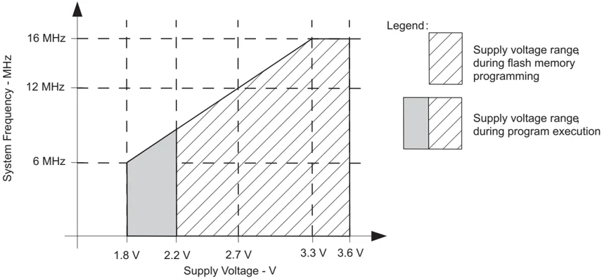
Note: Minimum processor frequency is defined by system clock. Flash program or erase operations require a minimum VCC of 2.2 V.
Figure 1. Safe Operating Area
SLAS735J – APRIL 2011 – REVISED MAY 2013
Electrical Characteristics
Active Mode Supply Current Into VCC Excluding External Current
over recommended ranges of supply voltage and operating free-air temperature (unless otherwise noted) (1)(2)
| PARAMETER | TEST CONDITIONS | TA | VCC | MIN | TYP | MAX | UNIT |
|---|---|---|---|---|---|---|---|
| IAM,1MHz Active mode (AM) current at 1 MHz | fDCO = fMCLK = fSMCLK = 1 MHz, fACLK = 0 Hz, Program executes in flash, BCCTL1 = CALBC1_1MHZ, DCOCTL = CALDCO_1MHZ, CPUOFF = 0, SCG0 = 0, SCG1 = 0, OSCOFF = 0 | 2.2 V | 230 | μA | |||
| 3 V | 330 | 420 |
(1) All inputs are tied to 0 V or to VCC. Outputs do not source or sink any current.
(2) The currents are characterized with a Micro Crystal CC4V-T1A SMD crystal with a load capacitance of 9 pF. The internal and external load capacitance is chosen to closely match the required 9 pF.
Typical Characteristics, Active Mode Supply Current (Into VCC)
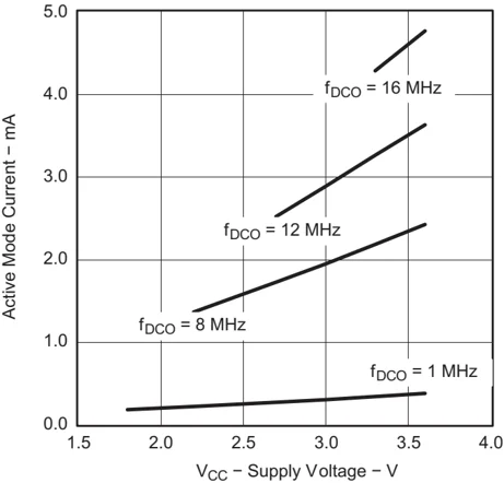
Figure 2. Active Mode Current vs VCC, TA = 25°C
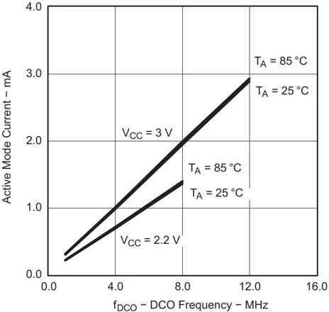
Figure 3. Active Mode Current vs DCO Frequency
22 Submit Documentation Feedback Copyright © 2011–2013, Texas Instruments Incorporated
Low-Power Mode Supply Currents (Into VCC) Excluding External Current
over recommended ranges of supply voltage and operating free-air temperature (unless otherwise noted) (1) (2)
| PARAMETER | TEST CONDITIONS | TA | VCC | MIN | TYP | MAX | UNIT |
|---|---|---|---|---|---|---|---|
| ILPM0,1MHz Low-power mode 0 (LPM0) current (3) | fMCLK = 0 MHz, fSMCLK = fDCO = 1 MHz, fACLK = 32768 Hz, BCSC1L1 = CALBC1_1MHZ, DCOCTL = CALDCO_1MHZ, CPUOFF = 1, SCG0 = 0, SCG1 = 0, OSCOFF = 0 | 25°C | 2.2 V | 56 | μA | ||
| ILPM2 Low-power mode 2 (LPM2) current (4) | fMCLK = fSMCLK = 0 MHz, fDCO = 1 MHz, fACLK = 32768 Hz, BCSC1L1 = CALBC1_1MHZ, DCOCTL = CALDCO_1MHZ, CPUOFF = 1, SCG0 = 0, SCG1 = 1, OSCOFF = 0 | 25°C | 2.2 V | 22 | μA | ||
| ILPM3,LFX1 Low-power mode 3 (LPM3) current (4) | fDCO = fMCLK = fSMCLK = 0 MHz, fACLK = 32768 Hz, CPUOFF = 1, SCG0 = 1, SCG1 = 1, OSCOFF = 0 | 25°C | 2.2 V | 0.7 | 1.5 | μA | |
| ILPM3,VLO Low-power mode 3 current, (LPM3) (4) | fDCO = fMCLK = fSMCLK = 0 MHz, fACLK from internal LF oscillator (VLO), CPUOFF = 1, SCG0 = 1, SCG1 = 1, OSCOFF = 0 | 25°C | 2.2 V | 0.5 | 0.7 | μA | |
| ILPM4 Low-power mode 4 (LPM4) current (5) | fDCO = fMCLK = fSMCLK = 0 MHz, fACLK = 0 Hz, CPUOFF = 1, SCG0 = 1, SCG1 = 1, OSCOFF = 1 | 25°C | 2.2 V | 0.1 | 0.5 | μA | |
| 85°C | 0.8 | 1.7 | μA |
(1) All inputs are tied to 0 V or to VCC. Outputs do not source or sink any current.
(2) The currents are characterized with a Micro Crystal CC4V-T1A SMD crystal with a load capacitance of 9 pF. The internal and external load capacitance is chosen to closely match the required 9 pF.
(3) Current for brownout and WDT clocked by SMCLK included.
(4) Current for brownout and WDT clocked by ACLK included.
(5) Current for brownout included.
Typical Characteristics, Low-Power Mode Supply Currents
over recommended ranges of supply voltage and operating free-air temperature (unless otherwise noted)
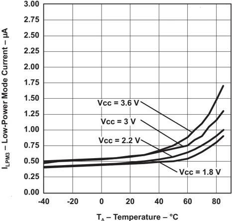
Figure 4. LPM3 Current vs Temperature
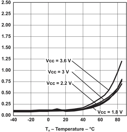
Figure 5. LPM4 Current vs Temperature
SLAS735J – APRIL 2011 – REVISED MAY 2013
Schmitt-Trigger Inputs, Ports Px
over recommended ranges of supply voltage and operating free-air temperature (unless otherwise noted)
| PARAMETER | TEST CONDITIONS | VCC | MIN | TYP | MAX | UNIT |
|---|---|---|---|---|---|---|
| VIT+ Positive-going input threshold voltage | 0.45 VCC | 0.75 VCC | V | |||
| 3 V | 1.35 | 2.25 | ||||
| VIT– Negative-going input threshold voltage | 0.25 VCC | 0.55 VCC | V | |||
| 3 V | 0.75 | 1.65 | ||||
| Vhys Input voltage hysteresis (VIT+ – VIT–) | 3 V | 0.3 | 1 | V | ||
| RPull Pullup/pulldown resistor | For pullup: VIN = VSSFor pulldown: VIN = VCC | 3 V | 20 | 35 | 50 | kΩ |
| CI Input capacitance | VIN = VSS or VCC | 5 | pF |
Leakage Current, Ports Px
over recommended ranges of supply voltage and operating free-air temperature (unless otherwise noted)
| PARAMETER | TEST CONDITIONS | VCC | MIN | MAX | UNIT |
|---|---|---|---|---|---|
| Ilkg(Px.y) High-impedance leakage current | (1) (2) | 3 V | ±50 | nA |
(1) The leakage current is measured with VSS or VCC applied to the corresponding pin(s), unless otherwise noted.
(2) The leakage of the digital port pins is measured individually. The port pin is selected for input and the pullup/pulldown resistor is disabled.
Outputs, Ports Px
over recommended ranges of supply voltage and operating free-air temperature (unless otherwise noted)
| PARAMETER | TEST CONDITIONS | VCC | MIN | TYP | MAX | UNIT |
|---|---|---|---|---|---|---|
| VOH High-level output voltage | I(OHmax) = –6 mA(1) | 3 V | VCC – 0.3 | V | ||
| VOL Low-level output voltage | I(OLmax) = 6 mA(1) | 3 V | VSS + 0.3 | V |
(1) The maximum total current, I(OHmax) and I(OLmax), for all outputs combined should not exceed ±48 mA to hold the maximum voltage drop specified.
Output Frequency, Ports Px
over recommended ranges of supply voltage and operating free-air temperature (unless otherwise noted)
| PARAMETER | TEST CONDITIONS | VCC | MIN | TYP | MAX | UNIT |
|---|---|---|---|---|---|---|
| fPx.y Port output frequency (with load) | Px.y, CL = 20 pF, RL = 1 kΩ(1) (2) | 3 V | 12 | MHz | ||
| fPort_CLK Clock output frequency | Px.y, CL = 20 pF(2) | 3 V | 16 | MHz |
(1) A resistive divider with two 0.5-kΩ resistors between VCC and VSS is used as load. The output is connected to the center tap of the divider.
(2) The output voltage reaches at least 10% and 90% VCC at the specified toggle frequency.
24 Submit Documentation Feedback Copyright © 2011–2013, Texas Instruments Incorporated
www.ti.com SLAS735J–APRIL 2011–REVISED MAY 2013
Typical Characteristics, Outputs
over recommended ranges of supply voltage and operating free-air temperature (unless otherwise noted)
TYPICAL LOW-LEVEL OUTPUT CURRENT vs LOW-LEVEL OUTPUT VOLTAGE
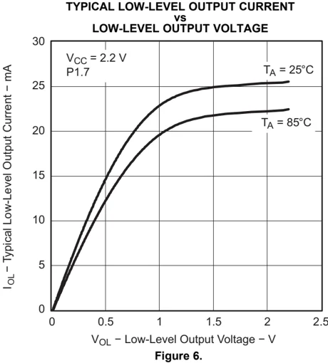
V$_{OL}$ – Low-Level Output Voltage – V Figure 6.
TYPICAL LOW-LEVEL OUTPUT CURRENT vs LOW-LEVEL OUTPUT VOLTAGE
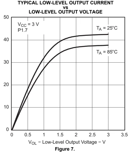
V$_{OL}$ – Low-Level Output Voltage – V Figure 7.
TYPICAL HIGH-LEVEL OUTPUT CURRENT vs HIGH-LEVEL OUTPUT VOLTAGE
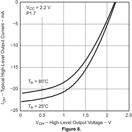
V$_{OH}$ – High-Level Output Voltage – V Figure 8.
TYPICAL HIGH-LEVEL OUTPUT CURRENT vs HIGH-LEVEL OUTPUT VOLTAGE
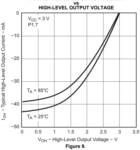
V$_{OH}$ – High-Level Output Voltage – V Figure 9.
Copyright © 2011–2013, Texas Instruments Incorporated Submit Documentation Feedback 25