Chapter 2 Operating Your Oscilloscope
By now, a user should understand the VERTICAL, HORIZONTAL and TRIGGER control systems and knows how to determine the system setup by status bar of a DS1000E, DS1000D series digital oscilloscope.
This chapter will go through all groups of front-panel buttons, knobs and menus; and further the knowledge of the operation by hints in this guide. It is recommended to perform all of the following exercises to get the most of the powerful measurement capabilities of the oscilloscope.
This chapter contains the following topics:
- To Set up the Vertical System ( CH1, CH2, MATH, REF, LA (for DS1000D series) OFF, Vertical \circledSPOSITION, Vertical \circledSSCALE )
- To Set up the Horizontal System ( MENU, Horizontal \circledSPOSITION, Horizontal \circledSSCALE )
- To Set up the Trigger System (\circledSLEVEL, MENU, 50%, FORCE)
- To Set up the Sampling System ( Acquire )
- To Set up the Display System ( Display )
- To Store and Recall ( Storage )
- To Set up the Utility System ( Utility )
- To Measure Automatically ( Measure )
- To Measure with Cursors ( Cursor )
- To Use Run Control Buttons ( AUTO, RUN/STOP )
Please refer to this chapter more carefully to get more information of the measurement and operation methods of DS1000E and DS1000D.
To Set up the Vertical System
Settings of the Channels
This series oscilloscopes offer dual channels. Each channel has an operation menu and it will pop up after pressing CH1 or CH2 button. The settings of all items in the menu is shown in the table below.
Figure 2- 1 Table 2- 1 The Channel menu (Page 1/2)
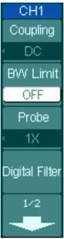
Figure 2- 2 Table 2- 2 The Channel Menu (Page 2/2)
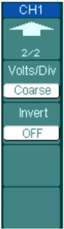
\begin{tabular}{|l|l|l|} \hline \textbf{Menu} & \textbf{Settings} & \textbf{Comments} \ \hline & 2/2 & Back to the previous menu page (The followings are the same, no more explanation) \ \hline Volts/Div & Coarse & Selects the resolution of the \circledSSCALE knob Defines a 1-2-5 sequence. To change the resolution to small steps between the coarse settings. \ \cline{2-3} & Fine & \ \hline Invert & ON & Turn on the invert function. Restore original display of the waveform. \ \cline{2-3} & OFF & \ \hline \end{tabular}
1. Channel coupling
To use Channel 1 as an example, input a sine wave signal with DC shift.
Press CH1\rightarrowCoupling\rightarrowAC to set "AC" coupling. It will pass AC component and blocks the DC component of the input signal. The waveform is displayed as Figure 2-3:
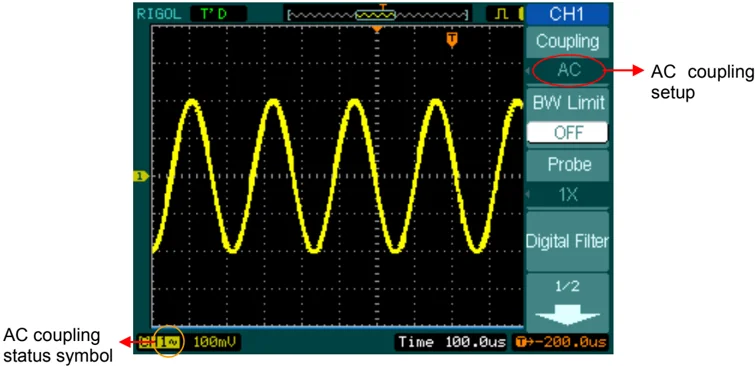
AC coupling setup
AC coupling status symbol
Figure 2- 3 AC coupling setting
Press CH1→Coupling→DC, to set “DC” coupling. It will pass both AC and DC components of the input signal. The waveform is displayed as Figure 2- 4:
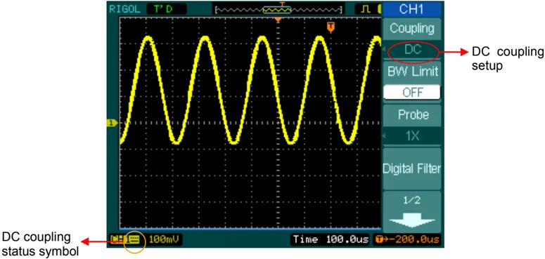
Figure 2- 4 DC coupling setting
Press CH1→Coupling→GND, to set “GND” coupling, it blocks the input signal. The screen displays as Figure 2-5:
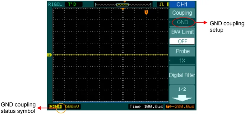
Figure 2- 5 GND coupling setting
User’s Guide for DS1000E, DS1000D Series
2. Set up the channel bandwidth limit
To take Channel1 as an example, input a signal containing high frequency component. Press CH1 \rightarrow BW Limit \rightarrow OFF, to set up bandwidth limit to "OFF" status. The oscilloscope is set to full bandwidth and passing the high frequency component in the signal. The waveform is displayed as Figure 2- 6:
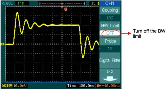
Figure 2- 6 Turn off the BW limit
Press CH1 \rightarrow BW Limit \rightarrow ON, to set up bandwidth limit to "ON" status. It will reject the frequency component higher than 20MHz.
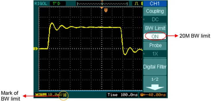
Figure 2- 7 Turn on the BW limit
3. Probe Attenuation Setting
The oscilloscope allows selecting the attenuation factor for the probe. The attenuation factor changes the vertical scaling of the oscilloscope so that the measurement results reflect the actual voltage levels at the probe tip.
To change (or check) the probe attenuation setting, press the CH1 or CH2 button (according to which channel in using). Press the Probe soft button to match the attenuation factor of the probe. This setting remains in effect until changed again.
Figure 2-8 shows an example for using a 1000:1 probe and its attenuation factor.
 Vertical volt/div.
Probe attenuation
Figure 2- 8 Use the 1000:1 attenuation
Table 2- 3 Probe setting \begin{tabular}{|l|l|} \hline \textbf{Probe attenuation factors} & \textbf{Corresponding settings} \ \hline 1:1 & 1X \ \hline 5:1 & 5X \ \hline 10:1 & 10X \ \hline 50:1 & 50X \ \hline 100:1 & 100X \ \hline 500:1 & 500X \ \hline 1000:1 & 1000X \ \hline \end{tabular}
4. Digital Filter settings
DS1000E, DS1000D series offer 4 types of digital filters (Low Pass Filter, High Pass Filter, Band Pass Filter and Band Reject Filter). In order to achieve a good filter effect, you can filter the special waveform frequency by setting up the range of filter bandwidth. Press CH1 \rightarrow Digital filter, display the digital filter menu. Turn (\circlearrowleft) knob to set high and low limit of frequency.
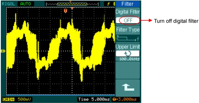
Figure 2- 9 The waveform when turning off digital filter
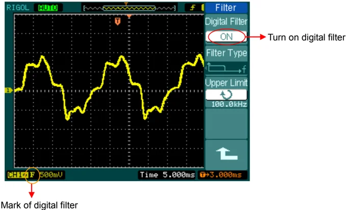
Mark of digital filter
Figure 2- 10 The waveform when turning on digital filter
Figure 2-11 Table 2-4 The Filter menu
| Menu | Settings | Comments |
|---|---|---|
| Digital Filter | ON | Turn on the digital filter |
| OFF | Turn off the digital filter | |
| Filter Type | ↑ ──→ f | Setup as LPF (Low Pass Filter) |
| ↑ ──→ f | Setup as HPF (High Pass Filter) | |
| ↑ ──→ f | Setup as BPF (Band Pass Filter) | |
| ↑ ──→ f | Setup as BRF (Band Reject Filter) | |
| Upper limit | ↻ | Turn (↻) knob to set high limit |
| Lower limit | ↻ | Turn (↻) knob to set low limit |
| ↑ ── | Back to higher level menu (The followings are the same) |
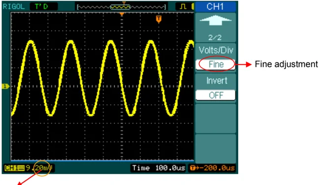
- Volts/Div settings
- The Volts/Div control has Coarse or Fine configuration. The Vertical Sensitivity is 2mV/div - 10V/div. Coarse: It is the default setting of Volts/Div in a 1-2-5-step sequence from 2mV/div, 5mV/div, 10mV/div, 20mV/div ........ 10V/div. Fine: This setting changes the vertical scale to small steps between the coarse settings. It will be helpful to adjust the waveform in smooth steps.
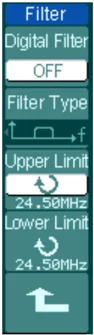
Figure 2-12 Fine configurations
Coarse/Fine Shortcut key: To change Coarse/Fine setting, not only by menu but also by pressing vertical SCALE knob
6. To invert a waveform
Invert turns the displayed waveform 180 degrees, as respect to the ground level. Figure 2- 13 and Figure 2- 14 show the changes after inversion.
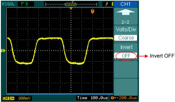
Figure 2- 13 The waveform before inversion
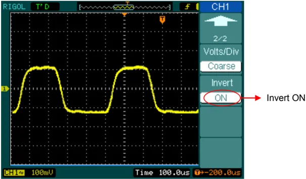
Figure 2- 14 The waveform after inversion
Math Functions
The mathematic functions include “Add”, “Subtract”, “Multiply” and “FFT” for Channel 1 and Channel 2. The mathematic result can be measured by grid and cursor. Press MATH button, the system enter the MATH interface as follows:
 Figure 2- 15
The Math function
Figure 2- 16 Table 2- 5 The Math menu
 \begin{tabular}{|l|l|l|}
\hline
\textbf{Menu} & \textbf{Settings} & \textbf{Comments} \
\hline
Operation & A+B & Add source A and source B \
& A-B & Subtract source B from source A \
& A×B & Multiply source B by source A \
& FFT & Fast Fourier Transform \
\hline
Source A & CH1 & Define CH1 or CH2 as source A \
& CH2 & \
\hline
Source B & CH1 & Define CH1 or CH2 as source B \
& CH2 & \
\hline
Invert & ON & Invert the MATH waveform. \
& OFF & Restore to original waveform display. \
\hline
\end{tabular}
1. Using the FFT
FFT (Fast Fourier Transform) transforms time domain signals to frequency domain signals. The horizontal axis shows the frequency and the vertical axis shows the amplitude dBVrms or Vrms. FFT function can not only to help you find crossfire problem and analog waveform distortion caused by nonlinear amplifier, but also can adjust the analog filter.
FFT waveforms are useful in the following applications:
● Measuring harmonic content and distortion in systems
● Characterizing noise in DC power supplies
● Analyzing vibration
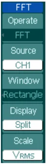
Press MATH \rightarrow Operate \rightarrow FFT, to display FFT menu.
Figure 2- 17 Table 2- 6 The FFT menu
\begin{tabular}{|l|l|l|} \hline \textbf{Menu} & \textbf{Settings} & \textbf{Comments} \ \hline Operate & A+B & Add source A to source B \ & A-B & Subtract source B from source A \ & A x B & Multiply source B by source A \ & FFT & Fast Fourier Transform \ \hline Source & CH1 & Define CH1 or CH2 as FFT source \ & CH2 & \ \hline Window & Rectangle & Select window for FFT \ & Hanning & \ & Hamming & \ & Blackman & \ \hline Display & Split & Display FFT waveform on half screen \ & Full screen & Display FFT waveform on full screen \ \hline Scale & Vrms & Set "Vrms" as vertical unit \ & dBVrms & Set "dBVrms" as vertical unit \ \hline \end{tabular}
Key points for FFT
Signals that have a DC component or offset can cause incorrect FFT waveform component magnitude values. To minimize the DC component, choose AC Coupling on the source signal.
To reduce random noise and aliases components in repetitive or single-shot events, set the oscilloscope acquisition mode to average.
To display FFT waveforms with a large dynamic range, use the dBVrms scale. The dBVrms scale displays component magnitudes using a log scale.
2. Selecting an FFT Window
The oscilloscopes provide four FFT windows. Each window is a trade-off between frequency resolution and amplitude accuracy. What you want to measure and your source signals characteristics help determine which window to use. Use the following guidelines to select the best window.
Table 2- 7 FFT Windows
Key points:
FFT Resolution: the quotient between sampling rate and number of FFT points. With a fixed FFT points, the lower sampling rate can insure better resolution.
Nyquist Frequency The highest frequency that any real-time digitizing oscilloscope can acquire without aliasing. It's normally half of the sample rate. This frequency is called the Nyquist frequency. Frequency above the Nyquist frequency will be under sampled, causing a situation known as aliasing.
REF Function
Reference Waveforms are saved waveforms to be selected for display. The reference function will be available after saving the selected waveform to non-volatile memory.
Press REF button to display reference waveform menu.
Figure 2- 18 Table 2- 8 REF Menu when using internal memory
Figure 2- 19 Table 2- 9 REF Menu when using external memory
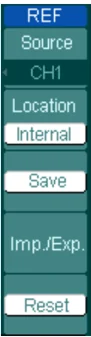
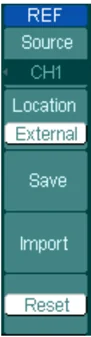
1. Import and Export
Press REF \rightarrow Imp./Exp. To enter the following menu.
Figure 2- 20 Table 2- 10 The Imp. /Exp. menu
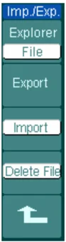
\begin{tabular}{|l|l|l|} \hline \textbf{Menu} & \textbf{Settings} & \textbf{Comments} \ \hline Explorer & Path & Switch to Path, directory or file \ \cline{2-3} & Directory & \ \cline{2-3} & File & \ \hline Export & & Export the REF file from internal memory to export memory (see table 2-11) \ \hline Import & & Import the REF file to internal memory \ \hline Delete File & & Delete file \ \hline \end{tabular}
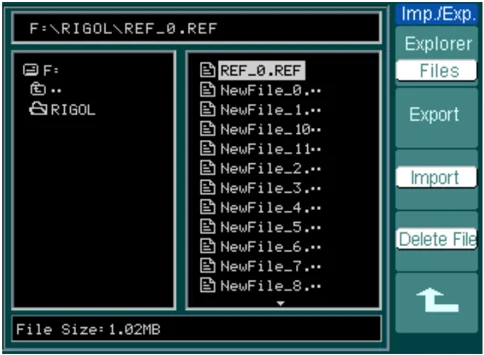
Figure 2- 21 Import /export interface
2. Export
Press REF \rightarrow Imp./Exp. \rightarrow Export to enter the following menu.
Figure 2- 22 Table 2- 11 The Export menu
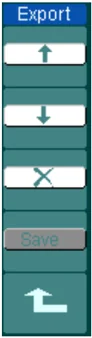
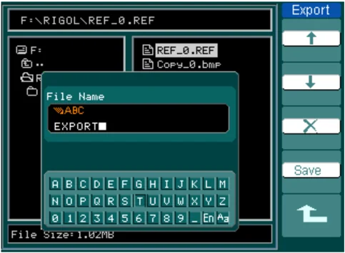
Figure 2- 23 Export interface
3. Save
Press REF→Save to enter the following menu.
Figure 2- 24 Table 2- 12 The Save Menu
\begin{tabular}{|l|l|l|} \hline \textbf{Menu} & \textbf{Settings} & \textbf{Comments} \ \hline Explorer & Path Directory File & Switch among Path, Directory and File \ \hline New File (Folder) & & Set up new file in Path and File. Set up new folder in directory. \ \hline Delete File(Folder) & & Delete file(Folder) \ \hline \end{tabular}
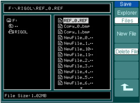
Figure 2- 25 Save interface
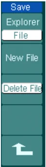
New File (or New Folder)
Press REF→Save→New File (or New Folder) and go to the following menu.
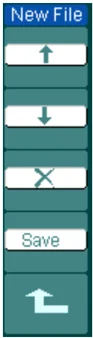
Figure 2- 26 Table 2- 13 The New File menu
\begin{tabular}{|l|l|l|} \hline \textbf{Menu} & \textbf{Settings} & \textbf{Comments} \ \hline \uparrow & & Move the cursor up \ \hline \downarrow & & Move the cursor down \ \hline X & & To delete chosen letter \ \hline Save & & Execute the operation \ \hline \end{tabular}
File name input box
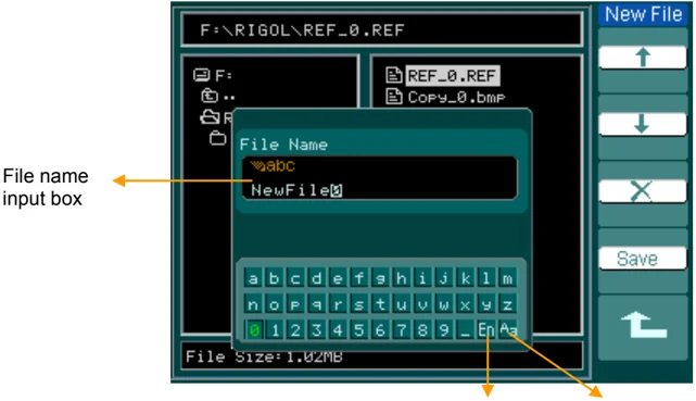
Switch Chinese/English Upper/Lower Case Switch
Figure 2- 27 Chinese Input interface
2-18 © 2008 RIGOL Technologies, Inc.
4. Import
Press REF \rightarrow Import and go to the following menu.
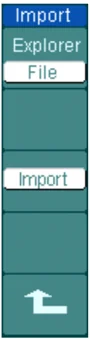
Figure 2- 28 Table 2- 14 The Import menu
\begin{tabular}{|l|l|l|} \hline \textbf{Menu} & \textbf{Settings} & \textbf{Comments} \ \hline Explorer & Path & Switch among Path, Directory and \ & Directory & File \ & File & \ \hline Import & & Import the REF file into internal \ & & memory \ \hline \end{tabular}
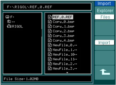
Figure 2- 29 Import interface
5. Displaying a Reference Waveform
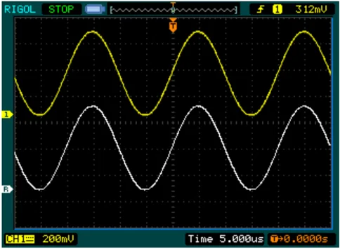
Figure 2- 30 Reference waveform display
- Push REF button to show the reference waveform menu.
- Press soft button No.1 to select the reference channel: CH1, CH2, MATH, FFT or LA (DS1000D series).
- Turn vertical POSITION and vertical SCALE to adjust the REF waveform to a suitable position.
- Press soft button No.2 to select the save location of REF waveform.
- Press soft button No.3 to save the waveform as REF.
NOTE: The reference function is not available in X-Y mode.
Set up LA Channel (Only for DS1000D Series)
16 digital channels logical analyzer are provided for DS1000D series, which can achieve mixed-signal measure in line with the dual analog channels. Single channel or group channels can be chosen ON or OFF, and also can set the size of waveform. Change display location of digital channel on screen and select threshold type.
Press \boxedLA function button and go to the following menu.
Figure 2- 31 Table 2- 15 The LA menu
 \begin{tabular}{|l|l|l|}
\hline
\textbf{Menu} & \textbf{Settings} & \textbf{Comments} \
\hline
D7-D0 & & Set up channel group D7-D0 (see table 2-16) \
\hline
D15-D8 & & set up channel group D15-D8 (see 2-17) \
\hline
Current & \circlearrowleft $<$D15-D0$>$ & Select channel by turning (\circlearrowleft) knob \
\hline
Threshold & TTL CMOS ECL User & Select mode of whole digital channels. The threshold voltage can set by user when in user-defined style. \
\hline
User & \circlearrowleft $<$Threshold Voltage$>$ & Set threshold voltage by turning (\circlearrowleft) knob. \
\hline
\end{tabular}
1. Display and re-line up the digital channels
(1) Press \boxedLA \rightarrow D7-D0 or D15-D8 and go to the group channel setting menu. Turn on or turn off the display of the digital channels.
(2) Press \boxedLA \rightarrow current and choose digital channel by turning (\circlearrowleft) knob. The chosen channel will display in red color.
(3) Turn vertical \otimesPOSITION knob to re-position the channel in screen.
The figure of menu shows as follow.
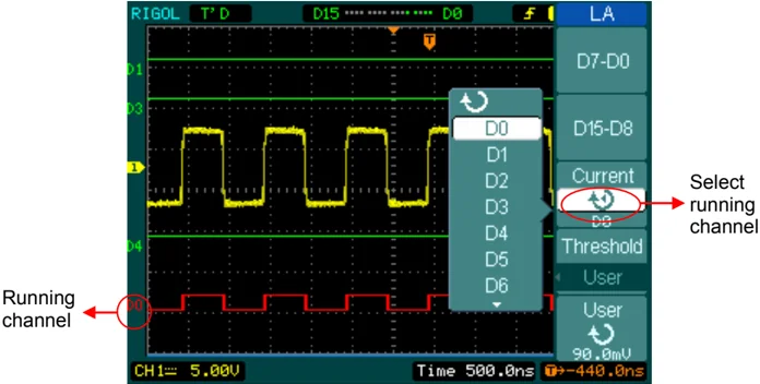
Figure 2-32 Turn on the digital channel
2. Set threshold mode of digital channels
Press LA → Threshold, select logic standard or User to define your own threshold voltage. The figure of menu shows as follow.
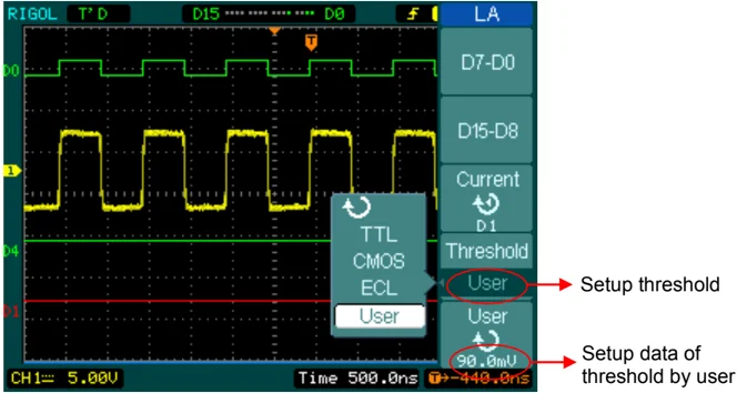
Figure 2-33 Set the threshold
Threshold explanation
| LOGIC STANDARD | TTL | CMOS | ECL | USER |
|---|---|---|---|---|
| THRESHOLD VLOTAGE | 1.4V | 2.5V | -1.3V | -8V to 8V |
2-22 © 2008 RIGOL Technologies, Inc.
Set up Channel Group
Press LA \rightarrow D7-D0 or D15-D8; Turn on/off the channel single, or in a group. Also you can change the size of waveforms in 8 bits as a group. See table 2-16 and 2-17.
Figure 2- 34 Table 2- 16 The Digital Channel menu (Page 1)
 \begin{tabular}{|l|l|l|}
\hline
\textbf{Menu} & \textbf{Settings} & \textbf{Comments} \
\hline
channel & D7-D0 & Turn on or off single channel of D7-D0 \
\hline
D7-D0 & Turn on \newline Turn off & Turn on or off all 8 channels together \
\hline
Size & \PiL \newline \sqcapL & Display 8 channels in a single screen \newline Display 16 channels in a single screen \
\hline
Reset & & Reset waveform of channel D7-D0 \
\hline
\end{tabular}
Figure 2- 35 Table 2- 17 The Digital Channel menu (Page 2)
 \begin{tabular}{|l|l|l|}
\hline
\textbf{Menu} & \textbf{Settings} & \textbf{Comments} \
\hline
channel & D15-D8 & Turn on or off single channel of D15-D8 \
\hline
D15-D8 & Turn on \newline Turn off & Turn on or off 8 channels together \
\hline
Size & \PiL \newline \sqcapL & Display 8 channels in a single screen \newline Display 16 channels in a single screen \
\hline
Reset & & Reset waveform of channel D15-D8 \
\hline
\end{tabular}
1. Turn on or off a digital channel
Press LA \rightarrow D7-D0 \rightarrow Channel, and choose the wanted channel by turning (knob icon) knob.
Press No. 1 soft button or push down (knob icon) knob to turn on /off the channel. When the channel is on, we can see the mark (■). When the channel is turned off; the mark will display as (□).
As figure 2-36 shows.
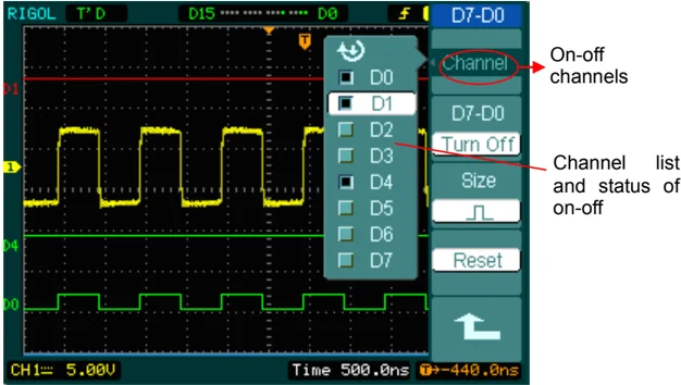
Figure 2- 36 Turn on or off the digital channel
2. Force turn on or off all digital channels
Press LA \rightarrow D7-D0 \rightarrow Turn On / Turn Off (or D15-D8 \rightarrow Turn On / Turn Off) will force to turn all the channels on/off. If you want to turn on/off any single channel instead, select the Channel by turning (knob icon) knob, then press No. 1 soft button or (knob icon) knob.
3. Set up the viewing size of digital channels
Press LA \rightarrow D7-D0 \rightarrow Size, or D15-D8 \rightarrow Size, to select wave size of logic channels. Select [pulse icon] to view 8 channels on the screen: Select [square wave icon] to view all of the 16 channels on the screen.
4. Reset the digital channels display
Press LA \rightarrow D7-D0 \rightarrow Reset, or D15-D8 \rightarrow Reset to reset the display of digital channels.
Turn on/off Channels
The CH1, CH2, Ext. Trigger and LA (DS1000D series) channels are input channels. All functionalities applied will be based on operating the instrument with channels. So MATH and REF can be regarded as relatively isolated channels.
To turn on/off any one of the channels, press the corresponding button on the front panel. The key backlight indicates the channel is currently active. Press the button again to turn the channel off. Or when channel is currently selected, press OFF will turn the channel off as well, and the key backlight also goes off.
The channel status symbol is displayed at the lower-left of the screen, which can help users to judge the channel status quickly.
Table 2- 18 Status of the channels
\begin{tabular}{|l|l|l|} \hline \textbf{Channel Mode} & \textbf{Settings} & \textbf{Status Indicator} \ \hline \multirow{3}{}{Channel 1 (CH1)} & ON & CH1 (yellow letter) \ \cline{2-3} & Selected & CH1 (black letter) \ \cline{2-3} & OFF & No indicator \ \hline \multirow{3}{}{Channel 2 (CH2)} & ON & CH2 ( blue letter) \ \cline{2-3} & Selected & CH2 (black letter) \ \cline{2-3} & OFF & No indicator \ \hline \multirow{3}{*}{MATH} & ON & Math (purple letter) \ \cline{2-3} & Selected & Math (black letter) \ \cline{2-3} & OFF & No indicator \ \hline \end{tabular}
NOTE: Pressing \boxedLA will turn all the digital channels on/off.