TL494 Pulse-Width-Modulation Control Circuits
1 Features
- Complete PWM power-control circuitry
- Uncommitted outputs for 200mA sink or source current
- Output control selects single-ended or push-pull operation
- Internal circuitry prohibits double pulse at either output
- Variable dead time provides control over total range
- Internal regulator provides a stable 5V reference supply with 5% tolerance
- Circuit architecture allows easy synchronization
2 Applications
- Desktop PCs
- Microwave ovens
- Power supplies: AC/DC, isolated, with or without PFC
- Server PSUs
- Solar micro-inverters
- Washing machines: low-end and high-end
- E-bikes
- Power: telecom/server AC/DC supplies: dual controller: analog
- Smoke detectors
- Solar power inverters
3 Description
The TL494 device incorporates all the functions required in the construction of a pulse-width-modulation (PWM) control circuit on a single chip. Designed primarily for power-supply control, this device offers the flexibility to tailor the power-supply control circuitry to a specific application.
The TL494 device contains two error amplifiers, an on-chip adjustable oscillator, a dead-time control (DTC) comparator, a pulse-steering control flip-flop, a 5V, 5%-precision regulator, and output-control circuits.
The error amplifiers exhibit a common-mode voltage range from –0.3V to VCC – 2V. The dead-time control comparator has a fixed offset that provides approximately 5% dead time. The on-chip oscillator can be bypassed by terminating RT to the reference output and providing a sawtooth input to CT, or it can drive the common circuits in synchronous multiple-rail power supplies.
The uncommitted output transistors provide either common-source or source-follower output capability. The TL494 device provides for push-pull or single-ended output operation, which can be selected through the output-control function. The architecture of this device prohibits the possibility of either output being pulsed twice during push-pull operation.
The TL494 device is characterized for operation from 0°C to 70°C. The TL494I device is characterized for operation from –40°C to 85°C.
Package Information
| PART NUMBER | PACKAGE(1) | PACKAGE SIZE(2) |
|---|---|---|
| TL494 | D (SOIC, 16) | 9.90mm × 3.91mm |
| N (PDIP, 16) | 19.30mm × 6.35mm | |
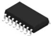
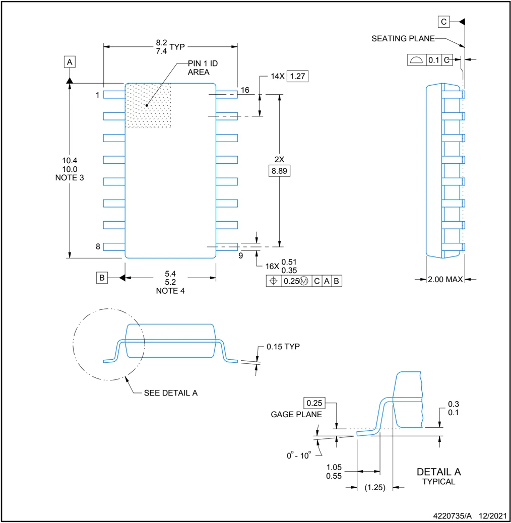
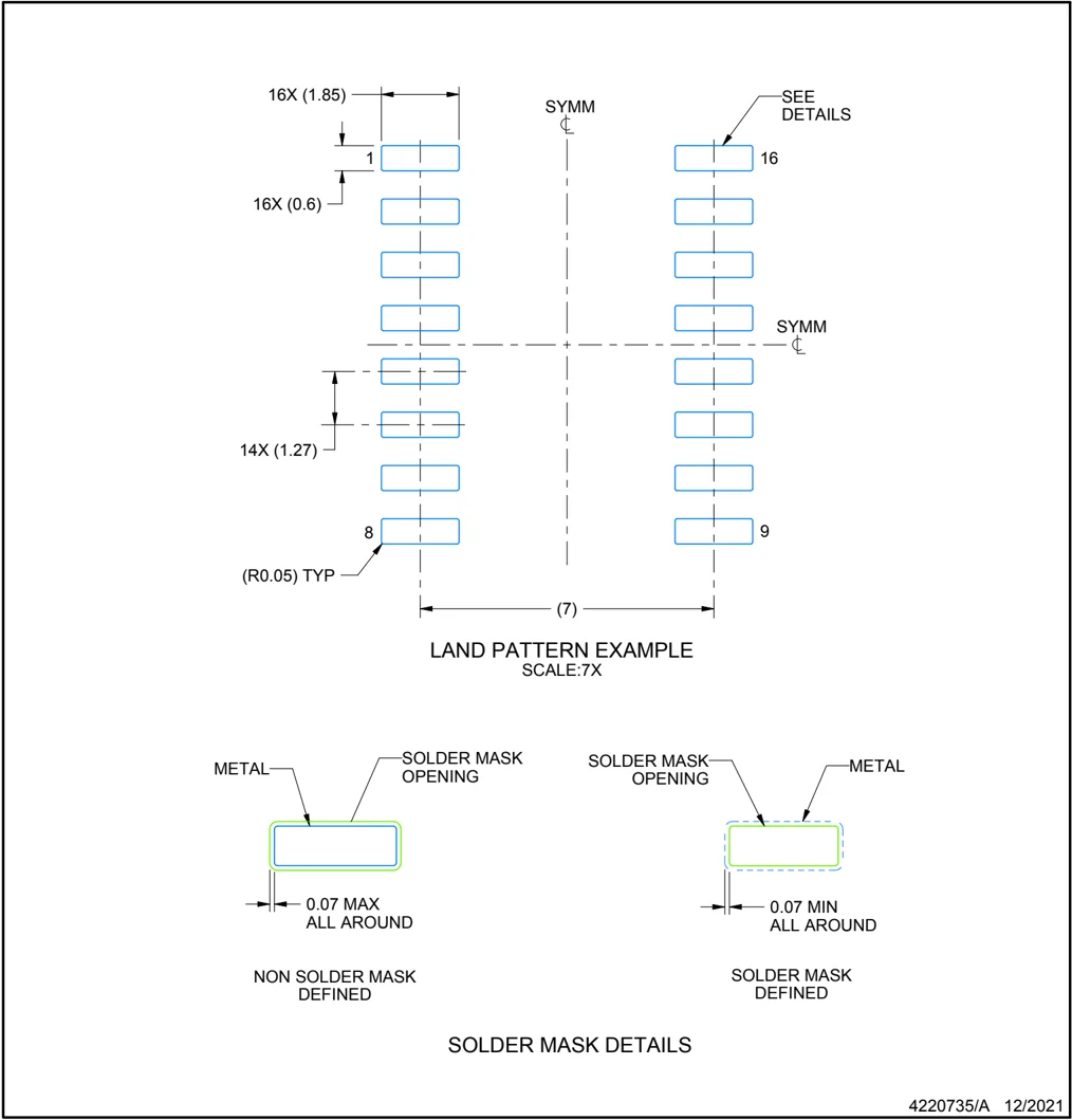
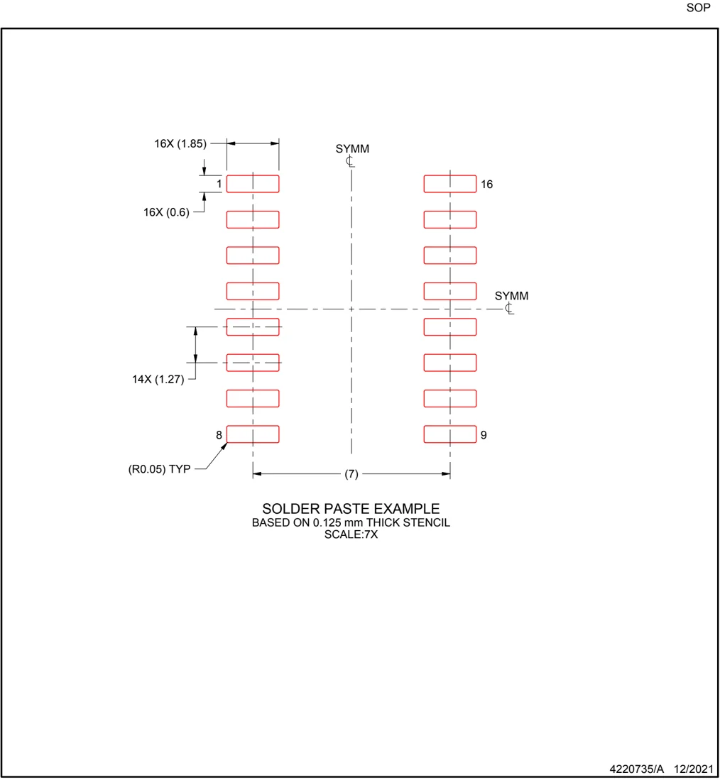
| NS (SOP, 16) | 10.30mm × 5.30mm | |
| PW (TSSOP, 16) | 5.00mm × 4.40mm |
(1) For all available packages, see the orderable addendum at the end of the datasheet.
(2) The package size (length × width) is a nominal value and includes pins, where applicable.

Simplified Block Diagram
An IMPORTANT NOTICE at the end of this data sheet addresses availability, warranty, changes, use in safety-critical applications, intellectual property matters and other important disclaimers. PRODUCTION DATA.
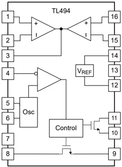
Table of Contents
- 1 Features ........ 1
- 2 Applications ........ 1
- 3 Description ........ 1
- 4 Pin Configuration and Functions ........ 3
- 5 Specifications ........ 4
- 5.1 Absolute Maximum Ratings ........ 4
- 5.2 ESD Ratings ........ 4
- 5.3 Recommended Operating Conditions ........ 4
- 5.4 Thermal Information ........ 4
- 5.5 Electrical Characteristics, Reference Section ........ 5
- 5.6 Electrical Characteristics, Oscillator Section ........ 5
- 5.7 Electrical Characteristics, Error-Amplifier Section ........ 5
- 5.8 Electrical Characteristics, Output Section ........ 6
- 5.9 Electrical Characteristics, Dead-Time Control Section ........ 6
- 5.10 Electrical Characteristics, PWM Comparator Section ........ 6
- 5.11 Electrical Characteristics, Total Device ........ 6
- 5.12 Switching Characteristics ........ 6
- 5.13 Typical Characteristics ........ 7
- 6 Parameter Measurement Information ........ 8
- 7 Detailed Description ........ 10
- 7.1 Overview ........ 10
- 7.2 Functional Block Diagram ........ 10
- 7.3 Feature Description ........ 10
- 7.4 Device Functional Modes ........ 12
- 8 Application and Implementation ........ 13
- 8.1 Application Information ........ 13
- 8.2 Typical Application ........ 13
- 8.3 Power Supply Recommendations ........ 19
- 8.4 Layout ........ 19
- 9 Device and Documentation Support ........ 21
- 9.1 Receiving Notification of Documentation Updates ........ 21
- 9.2 Support Resources ........ 21
- 9.3 Documentation Support ........ 21
- 9.4 Trademarks ........ 21
- 9.5 Electrostatic Discharge Caution ........ 21
- 9.6 Glossary ........ 21
- 10 Revision History ........ 21
- 11 Mechanical, Packaging, and Orderable Information ........ 22
2 Submit Document Feedback
4 Pin Configuration and Functions
 Not to scale
Figure 4-1. D, N, NS, or PW Package 16-Pin SOIC, PDIP, SO, or TSSOP Top View
Table 4-1. Pin Functions
(1) I = input, O = output
5 Specifications
5.1 Absolute Maximum Ratings
over operating free-air temperature range (unless otherwise noted)(1)
| MIN | MAX | UNIT | |
|---|---|---|---|
| VCC Supply voltage(2) | 41 | V | |
| VI Amplifier input voltage | VCC + 0.3 | V | |
| VO Collector output voltage | 41 | V | |
| IO Collector output current | 250 | mA | |
| Lead temperature 1,6mm (1/16 inch) from case for 10 seconds | 260 | °C | |
| Tstg Storage temperature range | –65 | 150 | °C |
(1) Operation outside the Absolute Maximum Ratings may cause permanent device damage. Absolute Maximum Ratings do not imply functional operation of the device at these or any other conditions beyond those listed under Recommended Operating Conditions. If used outside the Recommended Operating Conditions but within the Absolute Maximum Ratings, the device may not be fully functional, and this may affect device reliability, functionality, performance, and shorten the device lifetime.
(2) All voltages are with respect to the network ground terminal.
5.2 ESD Ratings
| MAX | UNIT | ||
|---|---|---|---|
| V(ESD) Electrostatic discharge | Human body model (HBM), per ANSI/ESDA/JEDEC JS-001, all pins | 500 | V |
| Charged device model (CDM), per JEDEC specification JESD22-C101, all pins | 200 |
5.3 Recommended Operating Conditions
| MIN | MAX | UNIT | ||
|---|---|---|---|---|
| VCC Supply voltage | 7 | 40 | V | |
| VI Amplifier input voltage | –0.3 | VCC – 2 | V | |
| VO Collector output voltage | 40 | V | ||
| Collector output current (each transistor) | 200 | mA | ||
| Current into feedback terminal | 0.3 | mA | ||
| fosc Oscillator frequency | 1 | 300 | kHz | |
| CT Timing capacitor | 0.47 | 10000 | nF | |
| RT Timing resistor | 1.8 | 500 | kΩ | |
| TA Operating free-air temperature | TL494C | 0 | 70 | °C |
| TL494I | –40 | 85 |
5.4 Thermal Information
| THERMAL METRIC(1) | TL494 | UNIT | |||
|---|---|---|---|---|---|
| D (SOIC) | N (PDIP) | NS (SO) | PW (TSSOP) | ||
| 16 PINS | 16 PINS | 16 PINS | 16 PINS | ||
| RθJA Junction-to-ambient thermal resistance | 88.0 | 73.8 | 95.3 | 114.0 | °C/W |
| RθJC(top) Junction-to-case (top) thermal resistance | 51.4 | 52.9 | 56.8 | 53.2 | °C/W |
| RθJB Junction-to-board thermal resistance | 50.6 | 49.2 | 62.0 | 71.8 | °C/W |
| ψJT Junction-to-top characterization parameter | 14.5 | 31.3 | 19.6 | 7.3 | °C/W |
| ψJB Junction-to-board characterization parameter | 50.1 | 48.6 | 61.3 | 71.2 | °C/W |
(1) For more information about traditional and new thermal metrics, see the Semiconductor and IC Package Thermal Metrics application note.
4 Submit Document Feedback
5.5 Electrical Characteristics, Reference Section
over recommended operating free-air temperature range, VCC = 15V, f = 10kHz (unless otherwise noted)
| PARAMETER | TEST CONDITIONS(1) | TL494C, TL494I | UNIT |
|---|---|---|---|
| MIN TYP(2) MAX | |||
| Output voltage (REF) | IO = 1mA | 4.75 5 5.25 | V |
| Input regulation | VCC = 7V to 40V | 2 25 | mV |
| Output regulation | IO = 1mA to 10mA | 6 15 | mV |
| Output voltage change with temperature | ΔTA = MIN to MAX | 2 10 | mV/V |
| Short-circuit output current(3) | REF = 0V | 35 | mA |
(1) For conditions shown as MIN or MAX, use the appropriate value specified under recommended operating conditions.
(2) All typical values, except for parameter changes with temperature, are at TA = 25°C.
(3) Duration of short circuit should not exceed one second.
5.6 Electrical Characteristics, Oscillator Section
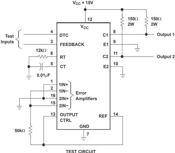
CT = 0.01μF, RT = 12kΩ (see Figure 6-1)
| PARAMETER | TEST CONDITIONS(1) | TL494C, TL494I | UNIT |
|---|---|---|---|
| MIN TYP(2) MAX | |||
| Frequency | 10 | kHz | |
| Standard deviation of frequency(3) | All values of VCC, CT, RT, and TA constant | 100 | Hz/kHz |
| Frequency change with voltage | VCC = 7V to 40V, TA = 25°C | 1 | Hz/kHz |
| Frequency change with temperature(4) | ΔTA = MIN to MAX | 50 | Hz/kHz |
(1) For conditions shown as MIN or MAX, use the appropriate value specified under recommended operating conditions.
(2) All typical values, except for parameter changes with temperature, are at TA = 25°C.
(3) Standard deviation is a measure of the statistical distribution about the mean as derived from the formula:
$$ \sigma = \sqrt{\frac{\sum_{n=1}^{N} \left[ x_n - \overline{x} \right]^2}{N - 1}} $$
(4) Temperature coefficient of timing capacitor and timing resistor are not taken into account.
5.7 Electrical Characteristics, Error-Amplifier Section
See Figure 6-2
| PARAMETER | TEST CONDITIONS | TL494C, TL494I | UNIT |
|---|---|---|---|
| MIN TYP(1) MAX | |||
| Input offset voltage | VO (FEEDBACK) = 2.5V | 2 10 | mV |
| Input offset current | VO (FEEDBACK) = 2.5V | 25 250 | nA |
| Input bias current | VO (FEEDBACK) = 2.5V | 0.2 1 | μA |
| Common-mode input voltage range | VCC = 7V to 40V | –0.3 to VCC – 2 | V |
| Open-loop voltage amplification | ΔVO = 3V, VO = 0.5V to 3.5V, RL = 2kΩ | 70 80 | dB |
| Unity-gain bandwidth | VO = 0.5V to 3.5V, RL = 2kΩ | 800 | kHz |
| Common-mode rejection ratio | ΔVO = 40V, TA = 25°C | 65 100 | dB |
| Output sink current (FEEDBACK) | VID = –15mV to –5V, V (FEEDBACK) = 0.7V | 0.3 0.7 | mA |
| Output source current (FEEDBACK) | VID = 15mV to 5V, V (FEEDBACK) = 3.5V | –2 | mA |
(1) All typical values, except for parameter changes with temperature, are at TA = 25°C.
5.8 Electrical Characteristics, Output Section
| PARAMETER | TEST CONDITIONS | MIN | TYP(1) | MAX | UNIT | |
|---|---|---|---|---|---|---|
| C1, C2 off-state current | VCE = 40V, VCC = 40V | 4 | 100 | μA | ||
| E1,E2 off-state current | VCC = VC = 40V, VE = 0 | –100 | μA | |||
| C1E1, C2E2 saturation voltage | Common source | VE = 0, IC = 200mA | 0.5 | 1.3 | V | |
| Source follower | VO(C1 or C2) = 15V, IE = –200mA | 1.65 | 2.5 | |||
| Output control input current | VI = Vref | 3.5 | mA |
(1) All typical values, except for temperature coefficient, are at TA = 25°C.
5.9 Electrical Characteristics, Dead-Time Control Section
See Figure 6-1
| PARAMETER | TEST CONDITIONS | MIN | TYP(1) | MAX | UNIT |
|---|---|---|---|---|---|
| Input bias current (DEAD-TIME CTRL) | VI = 0 to 5.25V | –0.006 | –10 | μA | |
| Maximum duty cycle, each output | VI (DEAD-TIME CTRL) = 0, CT = 0.01μF, RT = 12kΩ | 45% | — | ||
| Input threshold voltage (DEAD-TIME CTRL) | Zero duty cycle | 2.5 | 3.3 | V | |
| Maximum duty cycle | 0 |
(1) All typical values, except for temperature coefficient, are at TA = 25°C.
5.10 Electrical Characteristics, PWM Comparator Section
See Figure 6-1
| PARAMETER | TEST CONDITIONS | MIN | TYP(1) | MAX | UNIT |
|---|---|---|---|---|---|
| Input threshold voltage (FEEDBACK) | Zero duty cyle | 3.4 | 4.5 | V | |
| Input sink current (FEEDBACK) | V (FEEDBACK) = 0.7V | 0.3 | 0.7 | mA |
(1) All typical values, except for temperature coefficient, are at TA = 25°C.
5.11 Electrical Characteristics, Total Device
| PARAMETER | TEST CONDITIONS | MIN | TYP(1) | MAX | UNIT | |
|---|---|---|---|---|---|---|
| Standby supply current | RT = Vref, All other inputs and outputs open | VCC = 15V | 1.62 | 10 | mA | |
| VCC = 40V | 1.68 | 15 | ||||
| Average supply current | VI (DEAD-TIME CTRL) = 2V, See Figure 6-1 | 2.2 | mA |
(1) All typical values, except for temperature coefficient, are at TA = 25°C.
5.12 Switching Characteristics
TA = 25°C
| PARAMETER | TEST CONDITIONS | MIN | TYP(1) | MAX | UNIT |
|---|---|---|---|---|---|
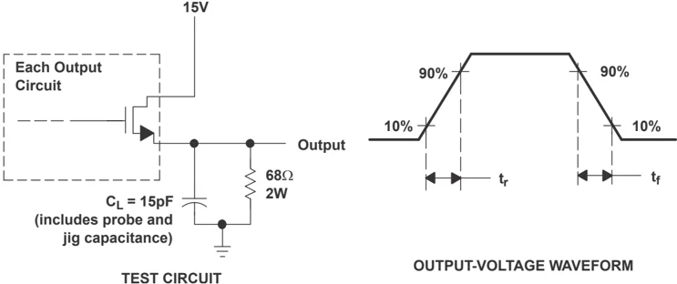
| Rise time | Common-source configuration, See Figure 6-3 | 70 | 200 | ns | |
| Fall time | 20 | 100 | ns | ||
| Rise time | Source-follower configuration, See Figure 6-4 | 85 | 200 | ns | |
| Fall time | 35 | 100 | ns |
(1) All typical values, except for temperature coefficient, are at TA = 25°C.
6 Submit Document Feedback

TEXAS INSTRUMENTS
SLVS074J – JANUARY 1983 – REVISED SEPTEMBER 2026
5.13 Typical Characteristics
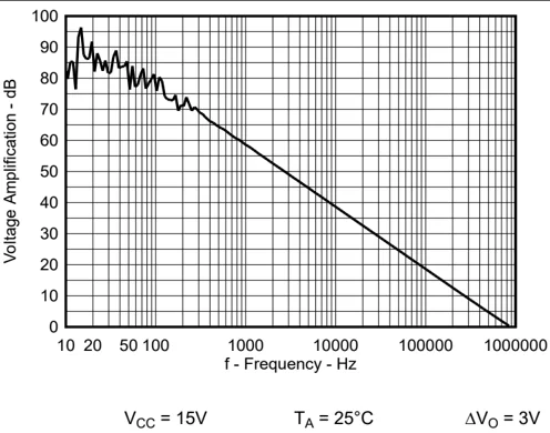
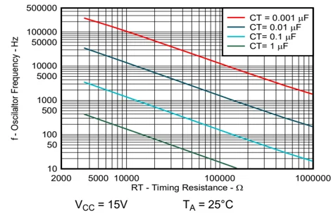
Figure 5-1. Oscillator Frequency vs Timing Resistance
Figure 5-2. Amplifier Voltage Amplification vs Frequency
Submit Document Feedback
7

6 Parameter Measurement Information
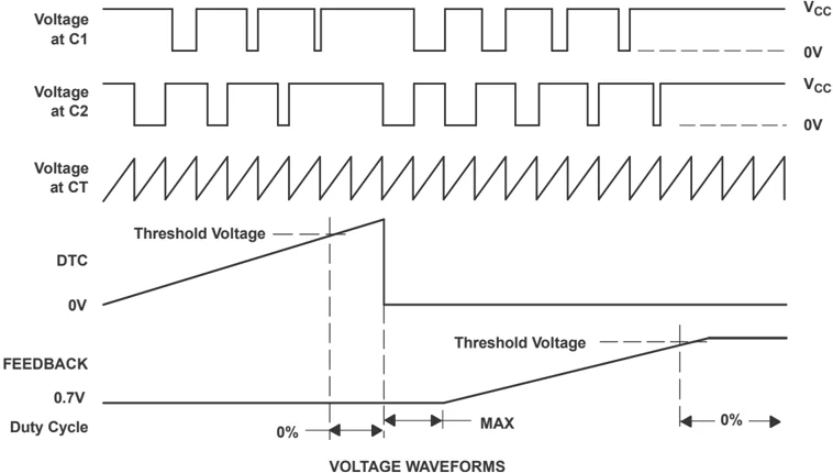
Figure 6-1. Operational Test Circuit and Waveforms
TEXAS INSTRUMENTS
SLVS074J – JANUARY 1983 – REVISED SEPTEMBER 2026
 Amplifier Under Test
V_I
FEEDBACK
V_ref
Other Amplifier
Figure 6-2. Amplifier Characteristics
 Each Output
Circuit
15V
68Ω
2W
Output
C_L = 15pF
(includes probe and
jig capacitance)
TEST CIRCUIT
t_f
t_r
90%
90%
10%
10%
OUTPUT-VOLTAGE WAVEFORM
Figure 6-3. Common-Emitter Configuration
 Each Output
Circuit
15V
C_L = 15pF
(includes probe and
jig capacitance)
68Ω
2W
Output
TEST CIRCUIT
90%
90%
10%
10%
t_r
t_f
OUTPUT-VOLTAGE WAVEFORM
Figure 6-4. Emitter-Follower Configuration
Submit Document Feedback 9
TL494
7 Detailed Description
7.1 Overview
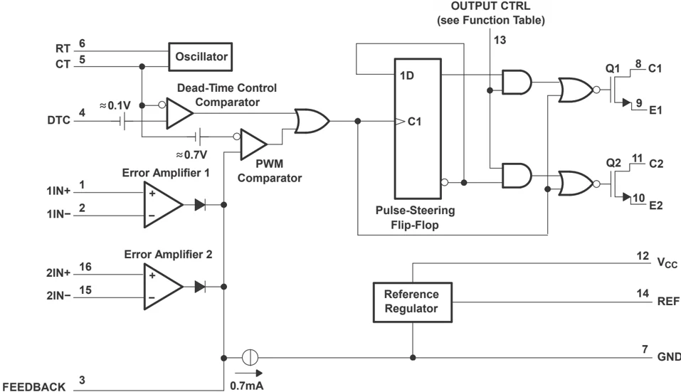
The design of the TL494 incorporates the primary building blocks required to control a switching power supply and addresses basic problems and reduces the amount of additional circuitry required in the total design. The TL494 is a fixed-frequency pulse-width-modulation (PWM) control circuit. The internal oscillator on the timing capacitor (CT) creates the sawtooth waveform. Achieve modulation of output pulses by comparing the sawtooth waveform to either of two control signals. The output stage is enabled during the time when the sawtooth voltage is greater than the voltage control signals. As the control signal increases, the time during which the sawtooth input is greater decreases; therefore, the output pulse duration decreases. A pulse-steering flip-flop alternately directs the modulated pulse to each of the two output transistors. For more information on the operation of the TL494, see the application notes located on ti.com.
7.2 Functional Block Diagram
7.3 Feature Description
7.3.1 5V Reference Regulator
The TL494 internal 5V reference regulator output is the REF pin. In addition to providing a stable reference, TL494 acts as a preregulator and establishes a stable supply to power the output-control logic, pulse-steering flip-flop, oscillator, dead-time control comparator, and PWM comparator. The regulator employs a band-gap circuit as the primary reference to maintain thermal stability of less than 100mV variation over the operating free-air temperature range from 0°C to 70°C. Short-circuit protection is provided to protect the internal reference and preregulator; 10mA of load current is available for additional bias circuits. The reference is internally programmed to an initial accuracy of ±5% and maintains a stability of less than 25mV variation over an input voltage range from 7V to 40V. For input voltages less than 7V, regulator output remains at 0V until the internal references reach a valid level, after which it transitions to 5V, resulting in more deterministic startup behavior as shown in Figure 8-8
10 Submit Document Feedback
TL494
7.3.2 Oscillator
The oscillator provides a positive sawtooth waveform to the dead-time and PWM comparators for comparison to the various control signals.
Program the frequency of the oscillator by selecting timing components $R_T$ and $C_T$. The oscillator charges the external timing capacitor, $C_T$, with a constant current. The external timing resistor, $R_T$ determines the constant current value and produces a linear-ramp voltage waveform. When the voltage across $C_T$ reaches 3V, the oscillator circuit discharges it, and the charging cycle reinitiates. Equation 2 determines the charging current.
$I_CHARGE = 3V/R_T \quad (2)$
The period of the sawtooth waveform is:
$T = \frac3V × C_TI_CHARGE \quad (3)$
The frequency of the oscillator becomes:
$f_OSC = 1/R_T × C_T \quad (4)$
However, the oscillator frequency is equal to the output frequency only for single-ended applications. For push-pull applications, the output frequency is one-half the oscillator frequency.
Single-ended applications:
$f = 1/R_T × C_T \quad (5)$
Push-pull applications:
$f = 1/2R_T × C_T \quad (6)$
7.3.3 Dead-time Control
The dead-time control input provides control of the minimum dead time (off time). The output of the comparator inhibits switching transistors Q1 and Q2 when the voltage at the input is greater than the ramp voltage of the oscillator. An internal offset of 110mV confirms a minimum dead time of approximately 3% with the dead time control input grounded. Applying a voltage to the dead-time control input can impose additional dead time. This provides a linear control of the dead time from its minimum of 3% to 100% as the input voltage varies from 0V to 3.3V, respectively. With full-range control, control the output from external sources without disrupting the error amplifiers. The dead-time control input is a relatively high-impedance input (I_I < 10\mu A) and must be used where additional control of the output duty cycle is required. However, for proper control, terminate the input. An open circuit is an undefined condition.
7.3.4 Comparator
The comparator is biased from the 5V reference regulator, providing isolation from the input supply for improved stability. The input of the comparator does not exhibit hysteresis, so protection against false triggering near the threshold must be provided. The comparator has a response time of 400ns from either of the control-signal inputs to the output transistors, with only 100mV of overdrive. This establishes positive control of the output within one-half cycle for operation within the recommended 300kHz range.
7.3.5 Pulse-Width Modulation (PWM)
The comparator also provides modulation control of the output pulse width. For this, the ramp voltage across timing capacitor $C_T$ is compared to the control signal present at the output of the error amplifiers. The timing capacitor input incorporates a series diode that is omitted from the control signal input. This requires the control
Submit Document Feedback 11
TL494
signal (error amplifier output) to be \cong 0.7V greater than the voltage across C$_T$ to inhibit the output logic, and confirms maximum duty-cycle operation without requiring the control voltage to sink to a true ground potential. The output pulse width varies from 97% of the period to 0 as the voltage present at the error amplifier output varies from 0.5V to 3.5V, respectively.
7.3.6 Error Amplifiers
Both high-gain error amplifiers receive bias from the V$_I$ supply rail. This permits a common-mode input voltage range from –0.3V to 2V less than V$_I$. Both amplifiers behave characteristically of a single-ended single-supply amplifier, in that each output is active high only. This allows each amplifier to pull up independently for a decreasing output pulse-width demand. With both outputs ORed together at the inverting input node of the PWM comparator, the amplifier demanding the minimum pulse out dominates. The amplifier outputs are biased low by a current sink to provide maximum pulse width out when both amplifiers are biased off.
7.3.7 Output-Control Input
The output-control input determines whether the output transistors operate in parallel or push-pull. This input is the supply source for the pulse-steering flip-flop. The output-control input is asynchronous and has direct control over the output, independent of the oscillator or pulse-steering flip-flop. The input condition is intended to be a fixed condition that the application defines. For parallel operation, ground the output-control input. This disables the pulse-steering flip-flop and inhibits its outputs. In this mode, both output transistors in parallel transmit the pulses seen at the output of the dead-time control/PWM comparator. For push-pull operation, connect the output-control input to the internal 5V reference regulator. Under this condition, each of the output transistors is enabled, alternately, by the pulse-steering flip-flop.
7.3.8 Output Transistors
Two output transistors are available on the TL494. Both transistors are configured as open drain/open source, and each can sink or source up to 200mA. The transistors have a saturation voltage of less than 1.3V in the common-source configuration and less than 2.5V in the source-follower configuration. The outputs are protected against excessive power dissipation to prevent damage and do not employ sufficient current limiting to allow them to operate as current-source outputs.
7.4 Device Functional Modes
When the OUTPUT CTRL pin is tied to ground, the TL494 is operating in single-ended or parallel mode. When the OUTPUT CTRL pin is tied to V$_{REF}$, the TL494 is operating in normal push-pull operation.
12 Submit Document Feedback
8 Application and Implementation
Note
Information in the following applications sections is not part of the TI component specification, and TI does not warrant its accuracy or completeness. TI’s customers are responsible for determining suitability of components for their purposes, as well as validating and testing their design implementation to confirm system functionality.
8.1 Application Information
The following design example uses the TL494 to create a 5V/10A power supply. For more information, see Designing Switching Voltage Regulators With the TL494.
8.2 Typical Application
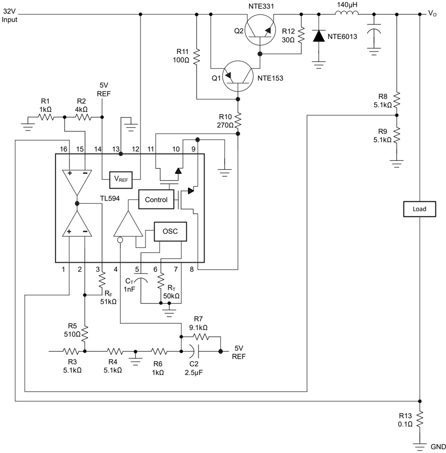
Figure 8-1. Switching and Control Sections

TL494
8.2.1 Design Requirements
- V_I = 32V
- V_O = 5V
- I_O = 10A
- f_OSC = 20kHz switching frequency
- V_R = 20mV peak-to-peak ($V_{RIPPLE}$)
- \Delta I_L = 1.5A inductor current change
8.2.2 Detailed Design Procedure
8.2.2.1 Input Power Source
The 32V DC power source for this supply uses a 120V input, 24V output transformer rated at 75VA. The 24V secondary winding feeds a full-wave bridge rectifier, followed by a current-limiting resistor (0.3\Omega) and two filter capacitors (see Figure 8-2).
 Figure 8-2. Input Power Source
Equation 7 and Equation 8 determine the output current and voltage.
$V_RECTIFIER = V_SECONDARY × \sqrt2 = 24V × \sqrt2 = 34V \quad (7)$
$I_RECTIFIER[AVG] \cong V_O/V_I × I_O \cong \frac5V32V × 10A = 1.6A \quad (8)$
The 3A/50V full-wave bridge rectifier meets these calculated conditions. Figure 8-1 shows the switching and control sections.
8.2.2.2 Control Circuits
8.2.2.2.1 Oscillator
Connecting an external capacitor and resistor to pins 5 and 6 controls the TL494 oscillator frequency. The oscillator is set to operate at 20kHz, using the component values calculated by Equation 4 and Equation 9:
Select C_T = 0.001\muF and calculate $R_T$:
$R_T = \frac1f_OSC × C_T = \frac1[20 × 10^3] × [0.001 × 10^-6] = 50k\Omega \quad (9)$
8.2.2.2.2 Error Amplifier
The error amplifier compares a sample of the 5V output to the reference and adjusts the PWM to maintain a constant output current (see Figure 8-3).
14 Submit Document Feedback

T EXAS INSTRUMENTS
SLVS074J– JANUARY 1983 – REVISED SEPTEMBER 2026
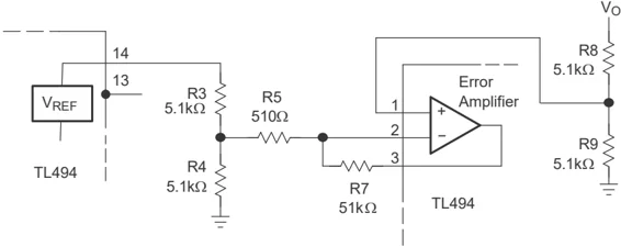
Figure 8-3. Error-Amplifier Section
The TL494 internal 5V reference is divided to 2.5V by R3 and R4. The output-voltage error signal also is divided to 2.5V by R8 and R9. If the output must be regulated to exactly 5.0V, use a 10k\Omega potentiometer in place of R8 to provide an adjustment.
To increase the stability of the error-amplifier circuit, the output of the error amplifier is fed back to the inverting input through R$_T$, reducing the gain to 101.
8.2.2.2.3 Current-Limiting Amplifier
The power supply id designed for a 10A load current and an I$_L$ swing of 1.5A, therefore, the short-circuit current is:
$I_SC = I_0 + I_L/2 = 10.75A \quad (10)$
Figure 8-4 shows the current-limiting circuit.
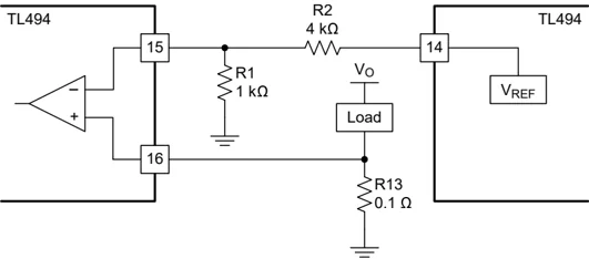
Figure 8-4. Current-Limiting Circuit
Resistors R1 and R2 set the reference of approximately 1V on the inverting input of the current-limiting amplifier. Resistor R13, in series with the load, applies 1 V to the noninverting terminal of the current-limiting amplifier when the load current reaches 10A. The output pulse duration reduces accordingly. Equation 11 calculate the value of R13.
$R13 = \frac1V10A = 0.1\Omega \quad (11)$
8.2.2.2.4 Soft Start and Dead Time
To reduce stress on the switching transistors at the start-up time, reduce the start-up surge that occurs as the output filter capacitor charges. The availability of the dead-time control makes implementation of a soft-start circuit relatively simple (see Figure 8-5).
Submit Document Feedback 15
TL494
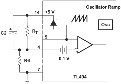
Figure 8-5. Soft-Start Circuit
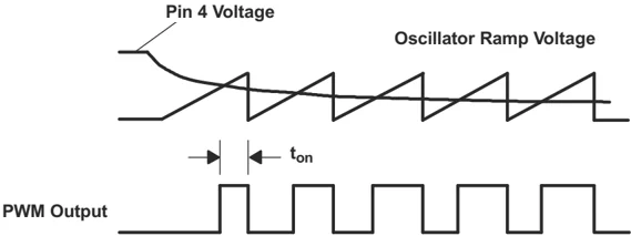
The soft-start circuit allows the pulse duration at the output to increase slowly (see Figure 8-5) by applying a negative slope waveform to the dead-time control input (pin 4).
Initially, capacitor C2 forces the dead-time control input to follow the 5V regulator, which disables the outputs (100% dead time). As the capacitor charges through R6, the output pulse duration slowly increases until the control loop takes command. With a resistor ratio of 1:10 for R6 and R7, the voltage at pin 4 after start-up is 0.1 × 5V, or 0.5V.
The soft-start time generally is in the range from 25 to 100 clock cycles. If selecting 50 clock cycles at a 20kHz switching rate, the soft-start time is:
$t = 1/f = \frac120kHz = 50\mus per clock cycle \quad (12)$
Calculate the value of the capacitor using:
$C2 = \fracsoft-start timeR6 = \frac50\mus × 50 cycles1k\Omega = 2.5\muF \quad (13)$
This helps eliminate any false signals created while applying power to the control circuit.
8.2.2.3 Inductor Calculations
Figure 8-6 shows the switching circuit.
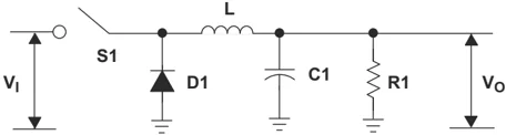
Figure 8-6. Switching Circuit
16 Submit Document Feedback Copyright © 2026 Texas Instruments Incorporated
The size of the inductor (L) required is:
$ d = duty cycle = \fracV_OV_I = \frac5V32V = 0.156 \qquad (14) $
$ f = 20kHz (design objective) \qquad (15) $
$ t_ON = time on (S1 closed) = \left(\frac1f\right) × d = 7.8\mus \qquad (16) $
$ t_OFF = time off (S1 open) = \left(\frac1f\right) - ton = 42.2\mus \qquad (17) $
$$ \begin{aligned} \text{L} &\approx (\text{V}{\text{I}} - \text{V}{\text{O}}) \times \frac{\text{t}{\text{ON}}}{\Delta\text{I}{\text{L}}} \ &\approx \frac{[(32\text{V} - 5\text{V}) \times 7.8\mu\text{s}]}{1.5\text{A}} \ &\approx 140.4\mu\text{H} \end{aligned} \qquad (18) $$
8.2.2.4 Output Capacitance Calculations
After calculating the filter inductor, calculate the value of the output filter capacitor to meet the output ripple requirements. Model an electrolytic capacitor as a series connection of an inductance, a resistance, and a capacitance. To provide good filtering, the ripple frequency must be far below the frequencies at which the series inductance becomes important. So, the two components of interest are the capacitance and the effective series resistance (ESR). Calculate the maximum ESR according to the relation between the specified peak-to-peak ripple voltage and the peak-to-peak ripple current.
$ ESR[max] = \frac\DeltaV_O[ripple]\DeltaI_L = \fracV1.5A \cong 0.067\Omega \qquad (19) $
Use Equation 20 to calculate the minimum capacitance of C3 necessary to maintain the V_O ripple voltage at less than the 100mV design objective.
$$ \text{C3} = \frac{\Delta\text{I}{\text{L}}}{8\text{f}\Delta\text{V}{\text{O}}} = \frac{1.5\text{A}}{8 \times 20 \times 10^3 \times 0.1\text{V}} = 94\mu\text{F} \qquad (20) $$
A 220mF, 60V capacitor is selected because the 60V capacitor has a maximum ESR of 0.074Ω and a maximum ripple current of 2.8A.
8.2.2.5 Transistor Power-Switch Calculations
The transistor power switch is constructed with an NTE153 pnp drive transistor and an NTE331 npn output transistor. These two power devices connect in a pnp hybrid Darlington circuit configuration (see Figure 8-7).
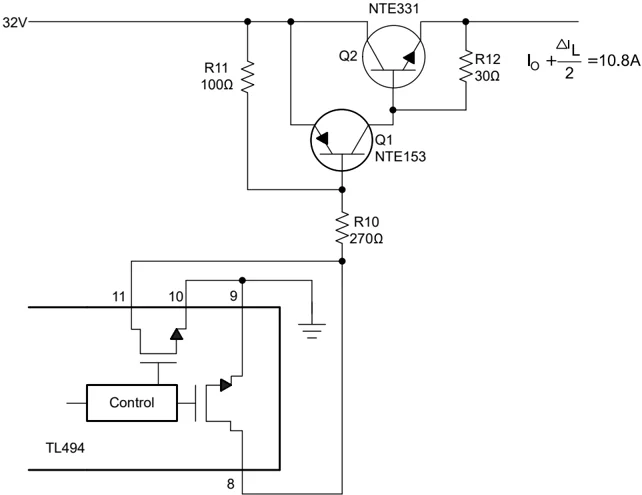
Figure 8-7. Power-Switch Section
The hybrid Darlington circuit must be saturated at a maximum output current of I_O + \Delta I_L/2 or 10.8 A. The Darlington $h_{FE}$ at 10.8 A must be high enough not to exceed the 250mA maximum output collector current of the TL494. Based on published NTE153 and NTE331 specifications, calcualte the required power-switch minimum drive using Equation 21 through Equation 23 to be 144mA:
h_FE[Q1] at I_C of 3A = 15 (21)
h_FE[Q2] at I_C of 10.0A = 5 (22)
i_B \geq \fracI_O + I_L/2h_FE[Q2] × h_FE[Q1] \geq 144mA (23)
Calculate the value of R10 using:
R10 \leq \fracV_I - [V_BE(Q1) + V_CE(TL494)]i_B = 32 - [1.5 + 0.7]/0.144 (24)
R10 \leq 207\Omega
Based on these calculations, the nearest standard resistor value of 220\Omega is selected for R10. Resistors R11 and R12 permit the discharge of carriers in switching transistors when turned off.
The power supply described demonstrates the flexibility of the TL494 PWM control circuit. This power-supply design demonstrates many of the power-supply control methods the TL494 provides, as well as the versatility of the control circuit.
TL494
www.ti.com SLVS074J – JANUARY 1983 – REVISED SEPTEMBER 2026
8.2 .3 Application Curves for Output Characteristics
 Figure 8-8. Reference Voltage vs Input Voltage
8.3 Power Supply Recommendations
The TL494 is designed to operate from an input voltage supply range from 7V to 40V. Well-regulate the input supply. If the input supply is located more than a few inches from the device, additional bulk capacitance can be required, in addition to the ceramic bypass capacitors. A tantalum capacitor with a value of 47µF is a typical choice, however this can vary depending upon the delivery of the output power.
8.4 Layout
8.4.1 Layout Guidelines
Always try to use a low EMI inductor with a ferrite type closed core, for example, toroid and encased E core inductors. Only use open core if they have low EMI characteristics and are located a bit more away from the low-power traces and components. Make the poles perpendicular to the PCB as well if using an open core. Stick cores usually emit the most unwanted noise.
8.4.1.1 Feedback Traces
Try to run the feedback trace as far from the inductor and noisy power traces as possible. Confirm that the feedback trace is as direct as possible and somewhat thick. These two sometimes involve a trade-off, but keeping it away from inductor EMI and other noise sources is the more critical of the two. Run the feedback trace on the side of the PCB opposite of the inductor with a ground plane separating the two.
8.4.1.2 Input/Output Capacitors
When using a low value ceramic input filter capacitor, locate the capacitor as close to the VCC pin of the IC as possible to eliminate as many trace inductance effects as possible and give the internal IC rail a cleaner voltage supply. Some designs require the use of a feed-forward capacitor connected from the output to the feedback pin as well, usually for stability reasons. In this case, position the capacitor as close to the IC as possible. Using surface-mount capacitors also reduces lead length and lessens the chance of noise coupling into the effective antenna created by through-hole components.
8.4.1.3 Compensation Components
For stability, place external compensation components close to the IC. Surface mount components are recommended here as well for the same reasons discussed for the filter capacitors. Do not locate surface-mount components very close to the inductor either.
8.4.1.4 Traces and Ground Planes
• Make all of the power (high current) traces as short, direct, and thick as possible. It is good practice on a standard PCB board to make the traces an absolute minimum of 15mils (0.381mm) per ampere.
• Confirm that the inductor, output capacitors, and output diode are as close to each other possible. This helps reduce the EMI radiated by the power traces due to the high switching currents through them and reduces

lead inductance and resistance as well, which in turn reduces noise spikes, ringing, and resistive losses that produce voltage errors.
• Connect the grounds of the IC, input capacitors, output capacitors, and output diode (if applicable) close together directly to a ground plane. Have a ground plane on both sides of the PCB to reduce noise by reducing ground loop errors and by absorbing more of the EMI radiated by the inductor.
• For multi-layer boards with more than two layers, use a ground plane to separate the power plane (where the power traces and components are) and the signal plane (where the feedback and compensation and components are) for improved performance.
• On multi-layer boards using vias is required to connect traces and different planes.
• It is good practice to use one standard via per 200mA of current if the trace must conduct a significant amount of current from one plane to the other.
• Arrange the components so that the switching current loops curl in the same direction. Due to the way switching regulators operate, there are two power states. One state when the switch is on and one when the switch is off. During each state there is a current loop made by the power components that are currently conducting. Place the power components so that during each of the two states the current loop is conducting in the same direction. This prevents magnetic field reversal caused by the traces between the two half-cycles and reduces radiated EMI.
8.4.2 Layout Example
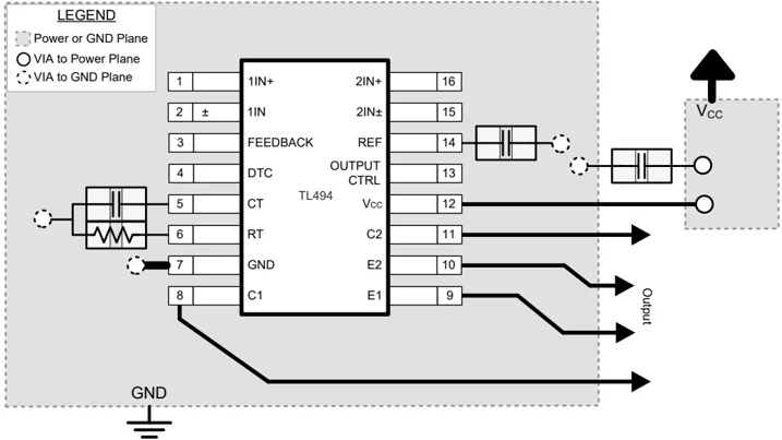
Figure 8-9. Operational Amplifier Board Layout for Noninverting Configuration
20 Submit Document Feedback Copyright © 2026 Texas Instruments Incorporated
9 Device and Documentation Support
9.1 Receiving Notification of Documentation Updates
To receive notification of documentation updates, navigate to the device product folder on ti.com. Click on Notifications to register and receive a weekly digest of any product information that has changed. For change details, review the revision history included in any revised document.
9.2 Support Resources
TI E2E™ support forums are an engineer's go-to source for fast, verified answers and design help — straight from the experts. Search existing answers or ask your own question to get the quick design help you need.
Linked content is provided "AS IS" by the respective contributors. They do not constitute TI specifications and do not necessarily reflect TI's views; see TI's Terms of Use.
9.3 Documentation Support
9.3.1 Related Documentation
- Texas Instruments, Designing Switching Voltage Regulators With the TL494 application note
- Texas Instruments, Semiconductor and IC Package Thermal Metrics application note
9.4 Trademarks
TI E2E™ is a trademark of Texas Instruments.
All trademarks are the property of their respective owners.
9.5 Electrostatic Discharge Caution

This integrated circuit can be damaged by ESD. Texas Instruments recommends that all integrated circuits be handled with appropriate precautions. Failure to observe proper handling and installation procedures can cause damage.
ESD damage can range from subtle performance degradation to complete device failure. Precision integrated circuits may be more susceptible to damage because very small parametric changes could cause the device not to meet its published specifications.
9.6 Glossary
TI Glossary This glossary lists and explains terms, acronyms, and definitions.
10 Revision History
NOTE: Page numbers for previous revisions may differ from page numbers in the current version.
Changes from Revision I (July 2022) to Revision J (September 2026)
| Change Description | Page |
|---|---|
| Updated the numbering format for tables, figures, and cross-references throughout the document. | 1 |
| Updated output transistor description and symbols from BJT to MOSFET throughout the document. | 1 |
| Changed values in the Thermal Information table for all packages. | 4 |
| Changed output regulation typical value from 1mV to 6mV. | 5 |
| Changed short-circuit output current typical value from 25mA to 35mA. | 5 |
| Changed frequency change with temperature max value from 10Hz/kHz to 50Hz/kHz. | 5 |
| Changed open-loop voltage amplification typical value from 95dB to 80dB. | 5 |
| Changed common-mode rejection ratio typical value from 80dB to 100dB. | 5 |
| Changed output C1, C2 off-state current typical value from 2μA to 4μA. | 6 |
| Changed output C1E1, C2E2 saturation voltage in common source configuration typical value from 1.1V to 0.5V. | 6 |
| Changed output C1E1, C2E2 saturation voltage in source follower configuration typical value from 1.5V to 1.65V. | 6 |
| Changed input bias current (DEAD-TIME CTRL) typical value from -2μA to -0.006μA. | 6 |
| Changed input threshold voltage (DEAD-TIME CTRL) typical value from 3V to 2.5V. | 6 |
| Changed input threshold voltage (FEEDBACK) typical value from 4V to 3.4V. | 6 |
- Changed standby supply current for VCC = 15V typical value from 6mA to 1.62mA ........ 6
- Changed standby supply current for VCC = 40V typical value from 9mA to 1.68mA ........ 6
- Changed average supply current typical value from 7.5mA to 2.2mA ........ 6
- Changed rise time in common source configuration typical value from 100ns to 70ns ........ 6
- Changed fall time in common source configuration typical value from 25ns to 20ns ........ 6
- Changed rise time in source follower configuration typical value from 100ns to 85ns ........ 6
- Changed fall time in source follower configuration typical value from 40ns to 35ns ........ 6
- Updated Oscillator Frequency vs Timing Resistance, Amplifier Voltage Amplification vs Frequency, and
- removed others ........ 7
- Updated description to align VREF behavior changes for input voltages less than 7V ........ 10
- Updated the formatting for inductor calculations ........ 16
- Updated reference voltage vs input voltage application curve ........ 19
Changes from Revision H (March 2017) to Revision I (July 2022) Page
- Updated the numbering format for tables, figures, and cross-references throughout the document ........ 1
11 Mechanical, Packaging, and Orderable Information
The following pages include mechanical packaging and orderable information. This information is the most current data available for the designated devices. This data is subject to change without notice and revision of this document. For browser based versions of this data sheet, refer to the left hand navigation.
22 Submit Document Feedback Copyright © 2026 Texas Instruments Incorporated
PACKAGE OPTION ADDENDUM
www.ti.com 24-Mar-2026
PACKAGING INFORMATION
| Orderable part number | Status (1) | Material type (2) | Package | Pins | Package qty | Carrier | RoHS (3) | Lead finish/ Ball material (4) | MSL rating/ Peak reflow (5) | Op temp (°C) | Part marking (6) | |
|---|---|---|---|---|---|---|---|---|---|---|---|---|
| TL494CD | Obsolete | Production | SOIC (D) | 16 | - | - | - | Call TI | Call TI | 0 to 70 | TL494C | |
| TL494CDR | Active | Production | SOIC (D) | 16 | 2500 | LARGE T&R | Yes | NIPDAU | SN | Level-1-260C-UNLIM | 0 to 70 | TL494C |
| TL494CDR.A | Active | Production | SOIC (D) | 16 | 2500 | LARGE T&R | Yes | NIPDAU | Level-1-260C-UNLIM | 0 to 70 | TL494C | |
| TL494CDRG4 | Obsolete | Production | SOIC (D) | 16 | - | - | - | Call TI | Call TI | 0 to 70 | TL494C | |
| TL494CN | Active | Production | PDIP (N) | 16 | 25 | TUBE | Yes | NIPDAU | N/A for Pkg Type | 0 to 70 | TL494CN | |
| TL494CN.A | Active | Production | PDIP (N) | 16 | 25 | TUBE | Yes | NIPDAU | N/A for Pkg Type | 0 to 70 | TL494CN | |
| TL494CNE4 | Active | Production | PDIP (N) | 16 | 25 | TUBE | Yes | NIPDAU | N/A for Pkg Type | 0 to 70 | TL494CN | |
| TL494CNSR | Active | Production | SOP (NS) | 16 | 2000 | LARGE T&R | Yes | NIPDAU | Level-1-260C-UNLIM | 0 to 70 | TL494 | |
| TL494CNSR.A | Active | Production | SOP (NS) | 16 | 2000 | LARGE T&R | Yes | NIPDAU | Level-1-260C-UNLIM | 0 to 70 | TL494 | |
| TL494CNSRG4 | Active | Production | SOP (NS) | 16 | 2000 | LARGE T&R | Yes | NIPDAU | Level-1-260C-UNLIM | 0 to 70 | TL494 | |
| TL494CPW | Obsolete | Production | TSSOP (PW) | 16 | - | - | - | Call TI | Call TI | 0 to 70 | T494 | |
| TL494CPWR | Active | Production | TSSOP (PW) | 16 | 2000 | LARGE T&R | Yes | NIPDAU | Level-1-260C-UNLIM | 0 to 70 | T494 | |
| TL494CPWR.A | Active | Production | TSSOP (PW) | 16 | 2000 | LARGE T&R | Yes | NIPDAU | Level-1-260C-UNLIM | 0 to 70 | T494 | |
| TL494ID | Obsolete | Production | SOIC (D) | 16 | - | - | - | Call TI | Call TI | -40 to 85 | TL494I | |
| TL494IDR | Active | Production | SOIC (D) | 16 | 2500 | LARGE T&R | Yes | NIPDAU | SN | Level-1-260C-UNLIM | -40 to 85 | TL494I |
| TL494IDR.A | Active | Production | SOIC (D) | 16 | 2500 | LARGE T&R | Yes | NIPDAU | Level-1-260C-UNLIM | -40 to 85 | TL494I | |
| TL494IDRG4 | Obsolete | Production | SOIC (D) | 16 | - | - | - | Call TI | Call TI | -40 to 85 | TL494I | |
| TL494IN | NRND | Production | PDIP (N) | 16 | 25 | TUBE | Yes | NIPDAU | N/A for Pkg Type | -40 to 85 | TL494IN | |
| TL494IN.A | NRND | Production | PDIP (N) | 16 | 25 | TUBE | Yes | NIPDAU | N/A for Pkg Type | -40 to 85 | TL494IN | |
| TL494INE4 | NRND | Production | PDIP (N) | 16 | 25 | TUBE | Yes | NIPDAU | N/A for Pkg Type | -40 to 85 | TL494IN |
(1) Status: For more details on status, see our product life cycle.
(2) Material type: When designated, preproduction parts are prototypes/experimental devices, and are not yet approved or released for full production. Testing and final process, including without limitation quality assurance, reliability performance testing, and/or process qualification, may not yet be complete, and this item is subject to further changes or possible discontinuation. If available for ordering, purchases will be subject to an additional waiver at checkout, and are intended for early internal evaluation purposes only. These items are sold without warranties of any kind.
(3) RoHS values: Yes, No, RoHS Exempt. See the TI RoHS Statement for additional information and value definition.
Addendum-Page 1

TEXAS INSTRUMENTS
PACKAGE OPTION ADDENDUM 24-Mar-2026
(4) Lead finish/Ball material: Parts may have multiple material finish options. Finish options are separated by a vertical ruled line. Lead finish/Ball material values may wrap to two lines if the finish value exceeds the maximum column width.
(5) MSL rating/Peak reflow: The moisture sensitivity level ratings and peak solder (reflow) temperatures. In the event that a part has multiple moisture sensitivity ratings, only the lowest level per JEDEC standards is shown. Refer to the shipping label for the actual reflow temperature that will be used to mount the part to the printed circuit board.
(6) Part marking: There may be an additional marking, which relates to the logo, the lot trace code information, or the environmental category of the part.
Multiple part markings will be inside parentheses. Only one part marking contained in parentheses and separated by a "~" will appear on a part. If a line is indented then it is a continuation of the previous line and the two combined represent the entire part marking for that device.
Important Information and Disclaimer: The information provided on this page represents TI's knowledge and belief as of the date that it is provided. TI bases its knowledge and belief on information provided by third parties, and makes no representation or warranty as to the accuracy of such information. Efforts are underway to better integrate information from third parties. TI has taken and continues to take reasonable steps to provide representative and accurate information but may not have conducted destructive testing or chemical analysis on incoming materials and chemicals. TI and TI suppliers consider certain information to be proprietary, and thus CAS numbers and other limited information may not be available for release.
In no event shall TI's liability arising out of such information exceed the total purchase price of the TI part(s) at issue in this document sold by TI to Customer on an annual basis.
Addendum-Page 2

PACKAGE MATERIALS INFORMATION
10-Aug-2026
TAPE AND REEL INFORMATION
REEL DIMENSIONS
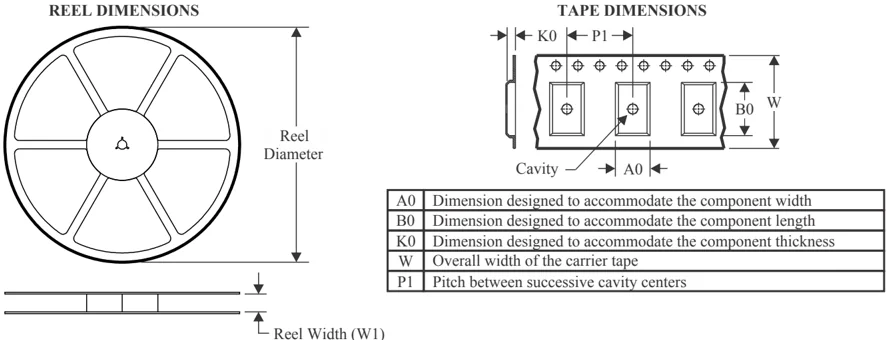
TAPE DIMENSIONS
| A0 | Dimension designed to accommodate the component width |
|---|---|
| B0 | Dimension designed to accommodate the component length |
| K0 | Dimension designed to accommodate the component thickness |
| W | Overall width of the carrier tape |
| P1 | Pitch between successive cavity centers |
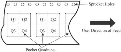
QUADRANT ASSIGNMENTS FOR PIN 1 ORIENTATION IN TAPE
*All dimensions are nominal
| Device | Package Type | Package Drawing | Pins | SPQ | Reel Diameter (mm) | Reel Width W1 (mm) | A0 (mm) | B0 (mm) | K0 (mm) | P1 (mm) | W (mm) | Pin1 Quadrant |
|---|---|---|---|---|---|---|---|---|---|---|---|---|
| TL494CDR | SOIC | D | 16 | 2500 | 330.0 | 16.4 | 6.5 | 10.3 | 2.1 | 8.0 | 16.0 | Q1 |
| TL494CNSR | SOP | NS | 16 | 2000 | 330.0 | 16.4 | 8.45 | 10.55 | 2.5 | 12.0 | 16.2 | Q1 |
| TL494CPWR | TSSOP | PW | 16 | 2000 | 330.0 | 12.4 | 6.9 | 5.6 | 1.6 | 8.0 | 12.0 | Q1 |
| TL494IDR | SOIC | D | 16 | 2500 | 330.0 | 16.4 | 6.5 | 10.3 | 2.1 | 8.0 | 16.0 | Q1 |
Pack Materials-Page 1
PACKAGE MATERIALS INFORMATION
10-Aug-2026
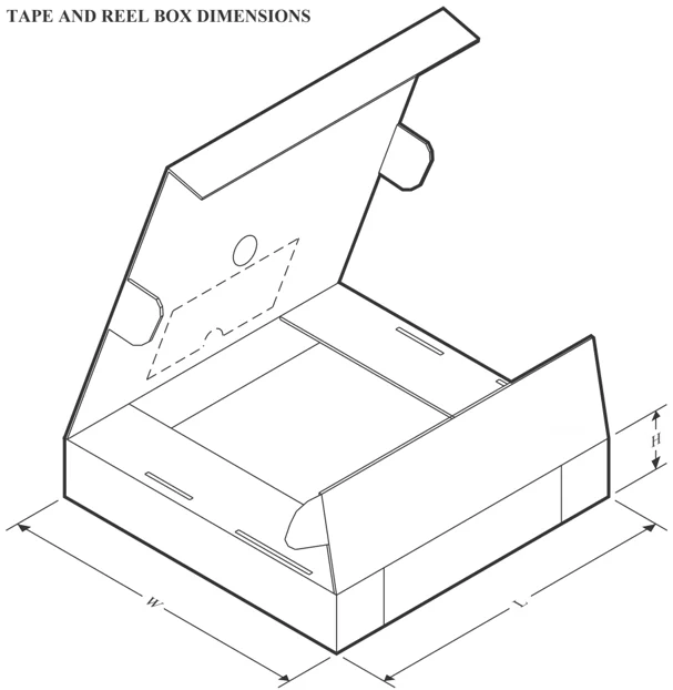
TAPE AND REEL BOX DIMENSIONS
*All dimensions are nominal
| Device | Package Type | Package Drawing | Pins | SPQ | Length (mm) | Width (mm) | Height (mm) |
|---|---|---|---|---|---|---|---|
| TL494CDR | SOIC | D | 16 | 2500 | 353.0 | 353.0 | 32.0 |
| TL494CNSR | SOP | NS | 16 | 2000 | 353.0 | 353.0 | 32.0 |
| TL494CPWR | TSSOP | PW | 16 | 2000 | 353.0 | 353.0 | 32.0 |
| TL494IDR | SOIC | D | 16 | 2500 | 353.0 | 353.0 | 32.0 |
Pack Materials-Page 2
PACKAGE MATERIALS INFORMATION
10-Aug-2026
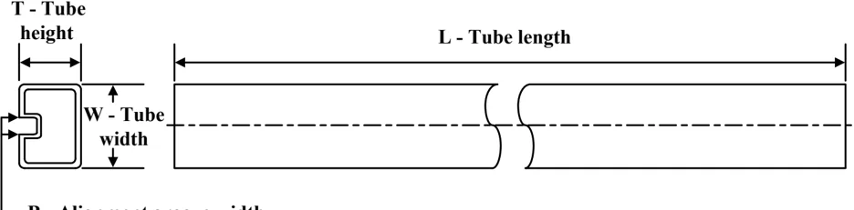
TUBE
*All dimensions are nominal
| Device | Package Name | Package Type | Pins | SPQ | L (mm) | W (mm) | T (μm) | B (mm) |
|---|---|---|---|---|---|---|---|---|
| TL494CN | N | PDIP | 16 | 25 | 506 | 13.97 | 11230 | 4.32 |
| TL494CN | N | PDIP | 16 | 25 | 506 | 13.97 | 11230 | 4.32 |
| TL494CN.A | N | PDIP | 16 | 25 | 506 | 13.97 | 11230 | 4.32 |
| TL494CN.A | N | PDIP | 16 | 25 | 506 | 13.97 | 11230 | 4.32 |
| TL494CNE4 | N | PDIP | 16 | 25 | 506 | 13.97 | 11230 | 4.32 |
| TL494CNE4 | N | PDIP | 16 | 25 | 506 | 13.97 | 11230 | 4.32 |
| TL494IN | N | PDIP | 16 | 25 | 506 | 13.97 | 11230 | 4.32 |
| TL494IN | N | PDIP | 16 | 25 | 506 | 13.97 | 11230 | 4.32 |
| TL494IN.A | N | PDIP | 16 | 25 | 506 | 13.97 | 11230 | 4.32 |
| TL494IN.A | N | PDIP | 16 | 25 | 506 | 13.97 | 11230 | 4.32 |
| TL494INE4 | N | PDIP | 16 | 25 | 506 | 13.97 | 11230 | 4.32 |
| TL494INE4 | N | PDIP | 16 | 25 | 506 | 13.97 | 11230 | 4.32 |
Pack Materials-Page 3
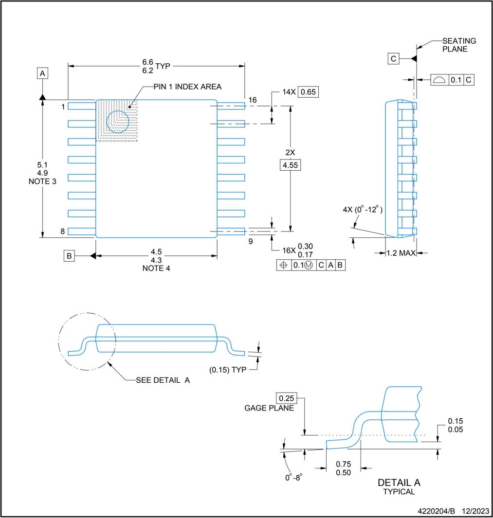
PACKAGE OUTLINE
PW0016A
TSSOP - 1.2 mm max height SMALL OUTLINE PACKAGE
4220204/B 12/2023
NOTES:
- All linear dimensions are in millimeters. Any dimensions in parenthesis are for reference only. Dimensioning and tolerancing per ASME Y14.5M.
- This drawing is subject to change without notice.
- This dimension does not include mold flash, protrusions, or gate burrs. Mold flash, protrusions, or gate burrs shall not exceed 0.15 mm per side.
- This dimension does not include interlead flash. Interlead flash shall not exceed 0.25 mm per side.
- Reference JEDEC registration MO-153.
TEXAS INSTRUMENTS

EXAMPLE BOARD LAYOUT
PW0016A TSSOP - 1.2 mm max height SMALL OUTLINE PACKAGE
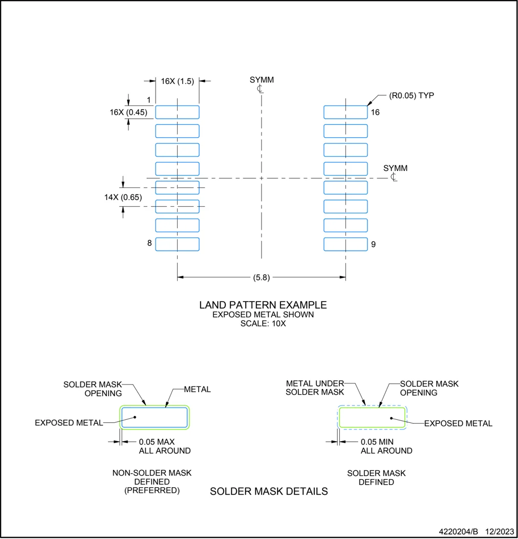
LAND PATTERN EXAMPLE EXPOSED METAL SHOWN SCALE: 10X
SOLDER MASK OPENING METAL EXPOSED METAL 0.05 MAX ALL AROUND NON-SOLDER MASK DEFINED (PREFERRED)
METAL UNDER SOLDER MASK SOLDER MASK OPENING EXPOSED METAL 0.05 MIN ALL AROUND SOLDER MASK DEFINED
SOLDER MASK DETAILS
4220204/B 12/2023
NOTES: (continued) 6. Publication IPC-7351 may have alternate designs. 7. Solder mask tolerances between and around signal pads can vary based on board fabrication site.
TEXAS INSTRUMENTS

EXAMPLE STENCIL DESIGN
PW0016A
TSSOP - 1.2 mm max height
SMALL OUTLINE PACKAGE
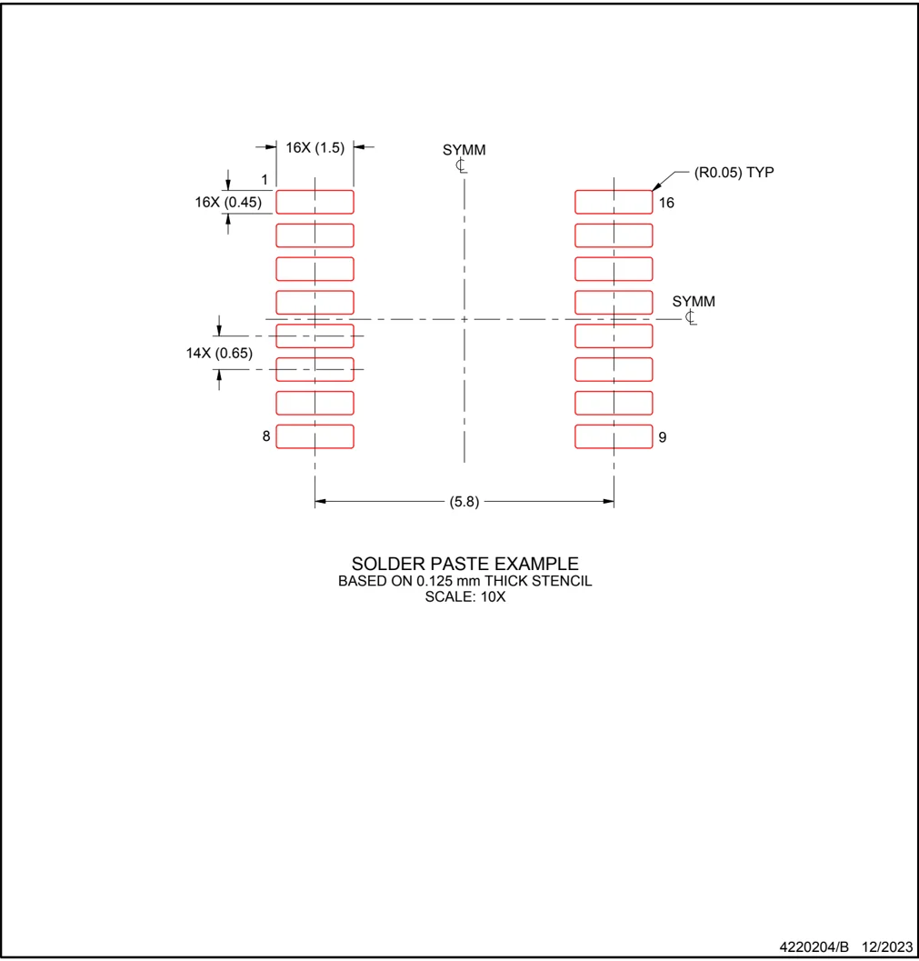
4220204/B 12/2023
NOTES: (continued)
-
Laser cutting apertures with trapezoidal walls and rounded corners may offer better paste release. IPC-7525 may have alternate design recommendations.
-
Board assembly site may have different recommendations for stencil design.
TEXAS INSTRUMENTS

MECHANICAL DATA
N (R-PDIP-T**)
16 PINS SHOWN
PLASTIC DUAL-IN-LINE PACKAGE
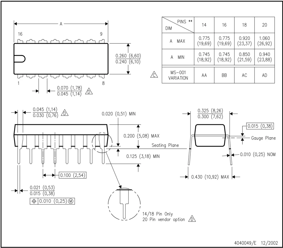
NOTES: A. All linear dimensions are in inches (millimeters). B. This drawing is subject to change without notice. △C Falls within JEDEC MS-001, except 18 and 20 pin minimum body length (Dim A). △D The 20 pin end lead shoulder width is a vendor option, either half or full width.
4040049/E 12/2002
TEXAS INSTRUMENTS

PACKAGE OUTLINE
NS0016A
SOP - 2.00 mm max height
SOP
4220735/A 12/2021
NOTES:
- All linear dimensions are in millimeters. Dimensions in parenthesis are for reference only. Dimensioning and tolerancing per ASME Y14.5M.
- This drawing is subject to change without notice.
- This dimension does not include mold flash, protrusions, or gate burrs. Mold flash, protrusions, or gate burrs shall not exceed 0.15 mm, per side.
- This dimension does not include interlead flash. Interlead flash shall not exceed 0.25 mm, per side.
TEXAS INSTRUMENTS

EXAMPLE BOARD LAYOUT
NS0016A
SOP - 2.00 mm max height SOP
NOTES: (continued)
- Publication IPC-7351 may have alternate designs.
- Solder mask tolerances between and around signal pads can vary based on board fabrication site.
4220735/A 12/2021

EXAMPLE STENCIL DESIGN
NS0016A SOP - 2.00 mm max height SOP
4220735/A 12/2021
NOTES: (continued)
- Laser cutting apertures with trapezoidal walls and rounded corners may offer better paste release. IPC-7525 may have alternate design recommendations.
- Board assembly site may have different recommendations for stencil design.
TEXAS INSTRUMENTS

MECHANICAL DATA
D (R-PDSO-G16) PLASTIC SMALL OUTLINE
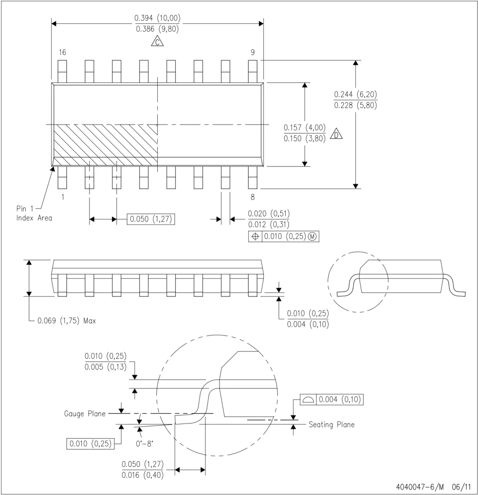
NOTES: A. All linear dimensions are in inches (millimeters). B. This drawing is subject to change without notice. C. Body length does not include mold flash, protrusions, or gate burrs. Mold flash, protrusions, or gate burrs shall not exceed 0.006 (0,15) each side. D. Body width does not include interlead flash. Interlead flash shall not exceed 0.017 (0,43) each side. E. Reference JEDEC MS-012 variation AC.
TEXAS INSTRUMENTS

IMPORTANT NOTICE AND DISCLAIMER
TI PROVIDES TECHNICAL AND RELIABILITY DATA (INCLUDING DATASHEETS), DESIGN RESOURCES (INCLUDING REFERENCE DESIGNS), APPLICATION OR OTHER DESIGN ADVICE, WEB TOOLS, SAFETY INFORMATION, AND OTHER RESOURCES “AS IS” AND WITH ALL FAULTS, AND DISCLAIMS ALL WARRANTIES, EXPRESS AND IMPLIED, INCLUDING WITHOUT LIMITATION ANY IMPLIED WARRANTIES OF MERCHANTABILITY, FITNESS FOR A PARTICULAR PURPOSE OR NON-INFRINGEMENT OF THIRD PARTY INTELLECTUAL PROPERTY RIGHTS.
These resources are intended for skilled developers designing with TI products. You are solely responsible for (1) selecting the appropriate TI products for your application, (2) designing, validating and testing your application, and (3) ensuring your application meets applicable standards, and any other safety, security, regulatory or other requirements.
These resources are subject to change without notice. TI grants you permission to use these resources only for development of an application that uses the TI products described in the resource. Other reproduction and display of these resources is prohibited. No license is granted to any other TI intellectual property right or to any third party intellectual property right. TI disclaims responsibility for, and you fully indemnify TI and its representatives against any claims, damages, costs, losses, and liabilities arising out of your use of these resources.
TI’s products are provided subject to TI’s Terms of Sale, TI’s General Quality Guidelines, or other applicable terms available either on ti.com or provided in conjunction with such TI products. TI’s provision of these resources does not expand or otherwise alter TI’s applicable warranties or warranty disclaimers for TI products. Unless TI explicitly designates a product as custom or customer-specified, TI products are standard, catalog, general purpose devices.
TI objects to and rejects any additional or different terms you may propose.
Copyright © 2026, Texas Instruments Incorporated Last updated 10/2025