MAX232 Dual EIA-232 Drivers and Receivers
1 Features
- Meets or exceeds TIA/EIA-232-F and ITU recommendation V.28
- Operates from a single 5V power supply with 1μF charge-pump capacitors
- Operates up to 120kbit/s
- Two drivers and two receivers
- ±30V Input levels
- Low supply current: 8mA typical
- ESD protection exceeds JESD 22
- 2000V Human-body model (A114-A)
- Upgrade with improved ESD (15kV HBM) and 0.1μF charge-pump capacitors is available with the MAX202 device
2 Applications
- TIA/EIA-232-F
- Battery-powered systems
- Terminals
- Modems
- Computers
3 Description
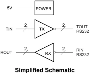
The MAX232 device is a dual driver/receiver that includes a capacitive voltage generator to supply TIA/EIA-232-F voltage levels from a single 5V supply. Each receiver converts TIA/EIA-232-F inputs to 5V TTL/CMOS levels. These receivers have a typical threshold of 1.3 V, a typical hysteresis of 0.5V, and can accept ±30V inputs. Each driver converts TTL/CMOS input levels into TIA/EIA-232-F levels.
Package Information
| PART NUMBER | PACKAGE(1) | PACKAGE SIZE(2) |
|---|---|---|
| MAX232 | SOIC (16) | 9.9mm × 6mm |
| SOIC (16) | 10.4mm × 10.3mm | |
| PDIP (16) | 19.3mm × 9mm | |
| SOP (16) | 10.2mm × 7.8 mm |
(1) For more Information, see Section 11. (2) The package size (length × width) is a nominal value and includes pins, where applicable.

Simplified Schematic
An IMPORTANT NOTICE at the end of this data sheet addresses availability, warranty, changes, use in safety-critical applications, intellectual property matters and other important disclaimers. PRODUCTION DATA.




MAX232 SLLS047N – FEBRUARY 1989 – REVISED FEBRUARY 2024
Table of Contents
- 1 Features ........ 1
- 2 Applications ........ 1
- 3 Description ........ 1
- 4 Pin Configuration and Functions ........ 3
- 5 Specifications ........ 4
- 5.1 Absolute Maximum Ratings(1) ........ 4
- 5.2 ESD Ratings ........ 4
- 5.3 Recommended Operating Conditions ........ 4
- 5.4 Thermal Information ........ 4
- 5.5 Electrical Characteristics, Device ........ 5
- 5.6 Electrical Characteristics, Driver ........ 5
- 5.7 Electrical Characteristics, Receiver ........ 5
- 5.8 Switching Characteristics ........ 5
- 5.9 Typical Characteristics ........ 6
- 6 Parameter Measurement Information ........ 7
- 7 Detailed Description ........ 9
- 7.1 Overview ........ 9
- 7.2 Functional Block Diagram ........ 9
- 7.3 Feature Description ........ 9
- 7.4 Device Functional Modes ........ 9
- 8 Application and Implementation ........ 10
- 8.1 Application Information ........ 10
- 8.2 Typical Application ........ 10
- 8.3 Power Supply Recommendations ........ 11
- 8.4 Layout ........ 11
- 9 Device and Documentation Support ........ 12
- 9.1 Receiving Notification of Documentation Updates ........ 12
- 9.2 Support Resources ........ 12
- 9.3 Trademarks ........ 12
- 9.4 Electrostatic Discharge Caution ........ 12
- 9.5 Glossary ........ 12
- 10 Revision History ........ 12
- 11 Mechanical, Packaging, and Orderable Information ........ 12
2 Submit Document Feedback Copyright © 2024 Texas Instruments Incorporated

4 Pin Configuration and Functions
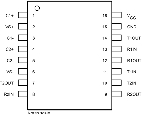
Figure 4-1. MAX232: D, DW, N or NS Package
MAX232I: D, DW, or N Package
(Top View)
Table 4-1. Pin Functions
| PIN | TYPE | DESCRIPTION |
|---|---|---|
| NAME | NO. | |
| C1+ | 1 | — Positive lead of C1 capacitor |
| VS+ | 2 | O Positive charge pump output for storage capacitor only |
| C1- | 3 | — Negative lead of C1 capacitor |
| C2+ | 4 | — Positive lead of C2 capacitor |
| C2- | 5 | — Negative lead of C2 capacitor |
| VS- | 6 | O Negative charge pump output for storage capacitor only |
| T2OUT | 7 | O RS232 line data output (to remote RS232 system) |
| R2IN | 8 | I RS232 line data input (from remote RS232 system) |
| R2OUT | 9 | O Logic data output (to UART) |
| T2IN | 10 | I Logic data input (from UART) |
| T1IN | 11 | I Logic data input (from UART) |
| R1IN | 13 | I RS232 line data input (from remote RS232 system) |
| T1OUT | 14 | O RS232 line data output (to remote RS232 system) |
| GND | 15 | — Ground |
| Vcc | 16 | — Supply Voltage, Connect to external 5V power supply |

5 Specifications
5.1 Absolute Maximum Ratings(1)
over operating free-air temperature range (unless otherwise noted)
| MIN | MAX | UNIT | |||
|---|---|---|---|---|---|
| VCC | Input Supply voltage range(2) | –0.3 | 6 | V | |
| VS+ | Positive output supply voltage range | VCC – 0.3 | 15 | V | |
| VS– | Negative output supply voltage range | –0.3 | –15 | V | |
| VI | Input voltage range | T1IN, T2IN | –0.3 | VCC + 0.3 | V |
| R1IN, R2IN | ±30 | ||||
| VO | Output voltage range | T1OUT, T2OUT | VS– – 0.3 | VS+ + 0.3 | V |
| R1OUT, R2OUT | –0.3 | VCC + 0.3 | |||
| Short-circuit duration | T1OUT, T2OUT | Unlimited | |||
| TJ | Operating virtual junction temperature | 150 | °C |
(1) Stresses beyond those listed under Absolute Maximum Ratings may cause permanent damage to the device. These are stress ratings only, and functional operation of the device at these or any other conditions beyond those indicated under Recommended Operating Conditions is not implied. Exposure to absolute-maximum-rated conditions for extended periods may affect device reliability.
(2) All voltages are with respect to network GND.
5.2 ESD Ratings
| MIN | MAX | UNIT | |||
|---|---|---|---|---|---|
| Tstg | Storage temperature range | -65 | 150 | °C | |
| V(ESD) | Electrostatic discharge | Human body model (HBM), per ANSI/ESDA/ JEDEC JS-001, all pins(1) | 0 | 2000 | V |
| Charged device model (CDM), per JEDEC specification JESD22-C101, all pins(2) | 0 | 1000 |
(1) JEDEC document JEP155 states that 500-V HBM allows safe manufacturing with a standard ESD control process.
(2) JEDEC document JEP157 states that 250-V CDM allows safe manufacturing with a standard ESD control process.
5.3 Recommended Operating Conditions
| MIN | NOM | MAX | UNIT | |||
|---|---|---|---|---|---|---|
| VCC | Supply voltage | 4.5 | 5 | 5.5 | V | |
| VIH | High-level input voltage (T1IN,T2IN) | 2 | V | |||
| VIL | Low-level input voltage (T1IN, T2IN) | 0.8 | V | |||
| R1IN, R2IN | Receiver input voltage | ±30 | V | |||
| TA | Operating free-air temperature | MAX232 | 0 | 70 | °C | |
| MAX232I | –40 | 85 |
5.4 Thermal Information
| THERMAL METRIC(1) | SOIC (D) 16 PINS | SOIC wide (DW) 16 PINS | PDIP (N) 16 PINS | SOP (NS) 16 PINS | UNIT | |
|---|---|---|---|---|---|---|
| RθJA | Junction-to-ambient thermal resistance | 84.6 | 71.7 | 60.6 | 88.5 | °C/W |
| RθJC(top) | Junction-to-case (top) thermal resistance | 43.5 | 37.6 | 48.1 | 46.2 | °C/W |
| RθJB | Junction-to-board thermal resistance | 43.2 | 36.8 | 40.6 | 50.7 | °C/W |
| ψJT | Junction-to-top characterization parameter | 10.4 | 13.3 | 27.5 | 13.5 | °C/W |
| ψJB | Junction-to-board characterization parameter | 42.8 | 36.4 | 40.3 | 50.3 | °C/W |
(1) For more information about traditional and new thermal metrics, see the IC Package Thermal Metrics application report (SPRA953).

5.5 Electrical Characteristics, Device
over recommended ranges of supply voltage and operating free-air temperature (unless otherwise noted) (see Figure 8-1)
| PARAMETER | TEST CONDITIONS⁽²⁾ | MIN | TYP⁽¹⁾ | MAX | UNIT |
|---|---|---|---|---|---|
| ICC Supply current | VCC = 5.5V, all outputs open, TA = 25°C | 8 | 10 | mA |
(1) All typical values are at VCC = 5V, and TA = 25°C.
(2) Test conditions are C1–C4 = 1μF at VCC = 5V ± 0.5V
5.6 Electrical Characteristics, Driver
over recommended ranges of supply voltage and operating free-air temperature (unless otherwise noted)
| PARAMETER | TEST CONDITIONS⁽²⁾ | MIN | TYP⁽¹⁾ | MAX | UNIT | |
|---|---|---|---|---|---|---|
| VOH High-level output voltage | T1OUT, T2OUT | RL = 3kΩ to GND | 5 | 7 | V | |
| VOL Low-level output voltage⁽²⁾ | T1OUT, T2OUT | RL = 3kΩ to GND | –7 | –5 | V | |
| rO Output resistance | T1OUT, T2OUT | VS+ = VS– = 0, VO = ±2V | 300 | Ω | ||
| IOS⁽³⁾ Short-circuit output current | T1OUT, T2OUT | VCC = 5.5V, VO = 0V | ±10 | mA | ||
| IIS Short-circuit input current | T1IN, T2IN | VI = 0 | 200 | μA |
(1) All typical values are at VCC = 5V, TA = 25°C.
(2) The algebraic convention, in which the least-positive (most negative) value is designated minimum, is used in this data sheet for logic voltage levels only.
(3) Not more than one output should be shorted at a time.
5.7 Electrical Characteristics, Receiver
over recommended ranges of supply voltage and operating free-air temperature (unless otherwise noted)
| PARAMETER | TEST CONDITIONS⁽³⁾ | MIN | TYP⁽¹⁾ | MAX | UNIT | |
|---|---|---|---|---|---|---|
| VOH High-level output voltage | R1OUT, R2OUT | IOH = –1mA | 3.5 | V | ||
| VOL Low-level output voltage⁽²⁾ | R1OUT, R2OUT | IOL = 3.2mA | 0.4 | V | ||
| VIT+ Receiver positive-going input threshold voltage | R1IN, R2IN | VCC = 5V, TA = 25°C | 1.7 | 2.4 | V | |
| VIT– Receiver negative-going input threshold voltage | R1IN, R2IN | VCC = 5V, TA = 25°C | 0.8 | 1.2 | V | |
| Vhys Input hysteresis voltage | R1IN, R2IN | VCC = 5V | 0.2 | 0.5 | 1 | V |
| rI Receiver input resistance | R1IN, R2IN | VCC = 5V, TA = 25°C | 3 | 5 | 7 | kΩ |
(1) All typical values are at VCC = 5V, TA = 25°C.
(2) The algebraic convention, in which the least-positive (most negative) value is designated minimum, is used in this data sheet for logic voltage levels only.
(3) Test conditions are C1–C4 = 1μF at VCC = 5V ± 0.5V.
5.8 Switching Characteristics
over recommended ranges of supply voltage and operating free-air temperature (unless otherwise noted)
| PARAMETER | TEST CONDITIONS⁽¹⁾ | MIN | TYP⁽¹⁾ | MAX | UNIT |
|---|---|---|---|---|---|
| SR Driver slew rate | RL = 3kΩ to 7kΩ, see Figure 6-2 | 30 | V/μs | ||
| SR(t) Driver transition region slew rate | see Figure 6-3 | 3 | V/μs | ||
| Data rate | One TOUT switching | 120 | kbit/s | ||
| tPLH® Receiver propagation delay time, low- to high-level output | TTL load, see Figure 6-1 | 500 | ns | ||
| tPHL® Receiver propagation delay time, high- to low-level output | TTL load, see Figure 6-1 | 500 | ns |
(1) Test conditions are C1–C4 = 1μF at VCC = 5V ± 0.5V.

MAX232
SLLS047N – FEBRUARY 1989 – REVISED FEBRUARY 2024
5.9 Typical Characteristics
 Figure 5-1. TOUT VOH & VOL vs Load Resistance, Both Drivers Loaded
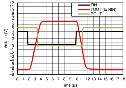
 Figure 5-2. Driver to Receiver Loopback Timing Waveform
6 Submit Document Feedback Copyright © 2024 Texas Instruments Incorporated
6 Parameter Measurement Information
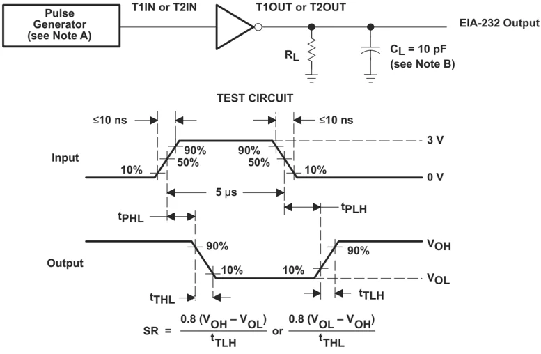
 A. The pulse generator has the following characteristics: Z_O = 50\Omega, duty cycle \leq 50%.
B. $C_L$ includes probe and jig capacitance.
C. All diodes are 1N3064 or equivalent.
Figure 6-1. Receiver Test Circuit and Waveforms for $t_{PHL}$ and $t_{PLH}$ Measurements
 A. The pulse generator has the following characteristics: Z_O = 50\Omega, duty cycle \leq 50%.
B. $C_L$ includes probe and jig capacitance.
Figure 6-2. Driver Test Circuit and Waveforms for $t_{PHL}$ and $t_{PLH}$ Measurements (5\mus Input)
MAX232 SLLS047N – FEBRUARY 1989 – REVISED FEBRUARY 2024
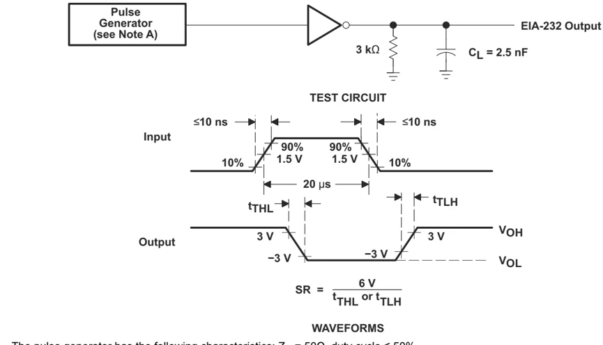
A. The pulse generator has the following characteristics: $Z_O$ = 50\Omega, duty cycle \leq 50%.
Figure 6-3. Test Circuit and Waveforms for $t_{THL}$ and $t_{TLH}$ Measurements (20µs Input)
8 Submit Document Feedback Copyright © 2024 Texas Instruments Incorporated

7 Detailed Description
7.1 Overview
The MAX232 device is a dual driver/receiver that includes a capacitive voltage generator using four capacitors to supply TIA/EIA-232-F voltage levels from a single 5-V supply. Each receiver converts TIA/EIA-232-F inputs to 5-V TTL/CMOS levels. These receivers have a typical threshold of 1.3 V, a typical hysteresis of 0.5 V, and can accept ±30-V inputs. Each driver converts TTL/CMOS input levels into TIA/EIA-232-F levels. The driver, receiver, and voltage-generator functions are available as cells in the Texas Instruments LinASIC™ library. Outputs are protected against shorts to ground.
7.2 Functional Block Diagram

7.3 Feature Description
7.3.1 Power
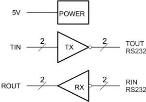
The power block increases and inverts the 5V supply for the RS232 driver using a charge pump that requires four 1µF external capacitors.
7.3.2 RS232 Driver
Two drivers interface standard logic level to RS232 levels. Internal pull up resistors on TIN inputs ensures a high input when the line is high impedance.
7.3.3 RS232 Receiver
Two receivers interface RS232 levels to standard logic levels. An open input will result in a high output on ROUT.
7.4 Device Functional Modes
7.4.1 VCC powered by 5V
The device will be in normal operation.
7.4.2 VCC unpowered
When MAX232 is unpowered, it can be safely connected to an active remote RS232 device.
7.4.3 Function Tables
Table 7-1. Each Driver
(1) H = high level, L = low level, X = irrelevant, Z = high impedance
MAX232 SLLS047N – FEBRUARY 1989 – REVISED FEBRUARY 2024
Table 7-2. Each Receiver
| INPUTS(1) | OUTPUT |
|---|---|
| RIN | ROUT |
| L | H |
| H | L |
| Open | H |
(1) H = high level, L = low level, X = irrelevant, Z = high impedance (off), Open = disconnected input or connected driver off
8 Application and Implementation
Note
Information in the following applications sections is not part of the TI component specification, and TI does not warrant its accuracy or completeness. TI’s customers are responsible for determining suitability of components for their purposes, as well as validating and testing their design implementation to confirm system functionality.
8.1 Application Information
For proper operation add capacitors as shown in Figure 8-1. Pins 9 through 12 connect to UART or general purpose logic lines. EIA-232 lines will connect to a connector or cable.
8.2 Typical Application
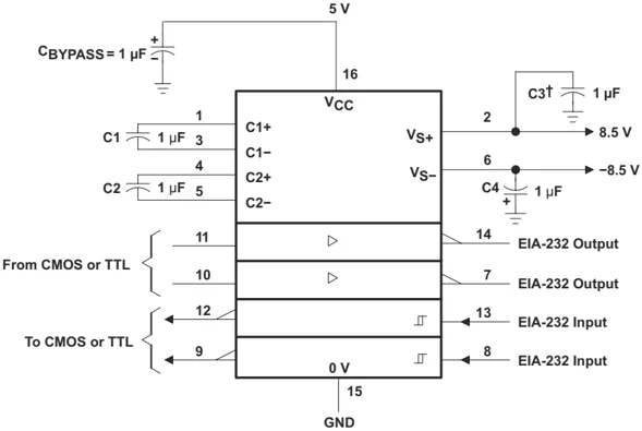
† C3 can be connected to VCC or GND.
NOTES: A. Resistor values shown are nominal. B. Nonpolarized ceramic capacitors are acceptable. If polarized tantalum or electrolytic capacitors are used, they should be connected as shown. In addition to the 1-μF capacitors shown, the MAX202 can operate with 0.1-μF capacitors.
Figure 8-1. Typical Operating Circuit
8.2.1 Design Requirements
- VCC minimum is 4.5V and maximum is 5.5V.
- Maximum recommended bit rate is 120kbps.
8.2.2 Detailed Design Procedure
Use 1uF tantalum or ceramic capacitors.
10 Submit Document Feedback Copyright © 2024 Texas Instruments Incorporated

8.2.3 Application Curves
 Figure 8-2. TOUT VOH & VOL vs Load Resistance, Both Drivers Loaded
 Figure 8-3. Driver to Receiver Loopback Timing Waveform
8.3 Power Supply Recommendations
The $V_{CC}$ voltage should be connected to the same power source used for logic device connected to TIN pins. $V_{CC}$ should be between 4.5V and 5.5V.
8.4 Layout
8.4.1 Layout Guidelines
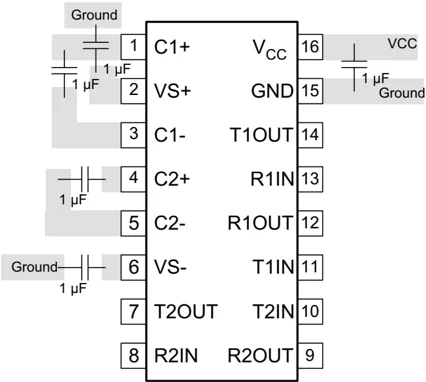
Keep the external capacitor traces short. This is more important on C1 and C2 nodes that have the fastest rise and fall times.
8.4.2 Layout Example
 Figure 8-4. Layout Schematic
Copyright © 2024 Texas Instruments Incorporated Submit Document Feedback 11
MAX232
SLLS047N – FEBRUARY 1989 – REVISED FEBRUARY 2024
9 Device and Documentation Support
9.1 Receiving Notification of Documentation Updates
To receive notification of documentation updates, navigate to the device product folder on ti.com. In the upper right corner, click on Alert me to register and receive a weekly digest of any product information that has changed. For change details, review the revision history included in any revised document.
9.2 Support Resources
TI E2E™ support forums are an engineer's go-to source for fast, verified answers and design help — straight from the experts. Search existing answers or ask your own question to get the quick design help you need.
Linked content is provided "AS IS" by the respective contributors. They do not constitute TI specifications and do not necessarily reflect TI's views; see TI's Terms of Use.
9.3 Trademarks
TI E2E™ is a trademark of Texas Instruments. All trademarks are the property of their respective owners.
9.4 Electrostatic Discharge Caution
 This integrated circuit can be damaged by ESD. Texas Instruments recommends that all integrated circuits be handled with appropriate precautions. Failure to observe proper handling and installation procedures can cause damage.
ESD damage can range from subtle performance degradation to complete device failure. Precision integrated circuits may be more susceptible to damage because very small parametric changes could cause the device not to meet its published specifications.
9.5 Glossary
TI Glossary This glossary lists and explains terms, acronyms, and definitions.
10 Revision History
Changes from Revision M (November 2004) to Revision N (February 2024) Page
- Changed the Handling Ratings table to the ESD Ratings table ........ 4
- Changed the Thermal Information table ........ 4
Changes from Revision L (March 2004) to Revision M (November 2014) Page
- Removed Ordering Information table ........ 1
- Added Handling Rating table, Feature Description section, Device Functional Modes, Application and Implementation section, Power Supply Recommendations section, Layout section, Device and Documentation Support section, and Mechanical, Packaging, and Orderable Information section ........ 1
- Changed the Device Information table to the Package Information table ........ 1
- Moved Tsig to Handling Ratings table ........ 4
11 Mechanical, Packaging, and Orderable Information
The following pages include mechanical packaging and orderable information. This information is the most current data available for the designated devices. This data is subject to change without notice and revision of this document. For browser based versions of this data sheet, refer to the left hand navigation.
12 Submit Document Feedback Copyright © 2024 Texas Instruments Incorporated

PACKAGE OPTION ADDENDUM
10-Mar-2026
PACKAGING INFORMATION
| Orderable part number | Status (1) | Material type (2) | Package | Pins | Package qty | Carrier | RoHS (3) | Lead finish/ Ball material (4) | MSL rating/ Peak reflow (5) | Op temp (°C) | Part marking (6) | |
|---|---|---|---|---|---|---|---|---|---|---|---|---|
| MAX232D | Obsolete | Production | SOIC (D) | 16 | - | - | Call TI | Call TI | 0 to 70 | MAX232 | ||
| MAX232DR | Active | Production | SOIC (D) | 16 | 2500 | LARGE T&R | Yes | NIPDAU | SN | Level-1-260C-UNLIM | 0 to 70 | MAX232 |
| MAX232DR.A | Active | Production | SOIC (D) | 16 | 2500 | LARGE T&R | Yes | NIPDAU | Level-1-260C-UNLIM | 0 to 70 | MAX232 | |
| MAX232DR.B | Active | Production | SOIC (D) | 16 | 2500 | LARGE T&R | Yes | NIPDAU | Level-1-260C-UNLIM | 0 to 70 | MAX232 | |
| MAX232DRG4 | Obsolete | Production | SOIC (D) | 16 | - | - | Call TI | Call TI | 0 to 70 | MAX232 | ||
| MAX232DW | Obsolete | Production | SOIC (DW) | 16 | - | - | Call TI | Call TI | 0 to 70 | MAX232 | ||
| MAX232DWG4 | Obsolete | Production | SOIC (DW) | 16 | - | - | Call TI | Call TI | 0 to 70 | MAX232 | ||
| MAX232DWR | Obsolete | Production | SOIC (DW) | 16 | - | - | Call TI | Call TI | 0 to 70 | MAX232 | ||
| MAX232DWRG4 | Obsolete | Production | SOIC (DW) | 16 | - | - | Call TI | Call TI | 0 to 70 | MAX232 | ||
| MAX232ID | Obsolete | Production | SOIC (D) | 16 | - | - | Call TI | Call TI | -40 to 85 | MAX232I | ||
| MAX232IDR | Active | Production | SOIC (D) | 16 | 2500 | LARGE T&R | Yes | NIPDAU | Level-1-260C-UNLIM | -40 to 85 | MAX232I | |
| MAX232IDR.A | Active | Production | SOIC (D) | 16 | 2500 | LARGE T&R | Yes | NIPDAU | Level-1-260C-UNLIM | -40 to 85 | MAX232I | |
| MAX232IDR.B | Active | Production | SOIC (D) | 16 | 2500 | LARGE T&R | Yes | NIPDAU | Level-1-260C-UNLIM | -40 to 85 | MAX232I | |
| MAX232IDW | Obsolete | Production | SOIC (DW) | 16 | - | - | Call TI | Call TI | -40 to 85 | MAX232I | ||
| MAX232IDWR | Active | Production | SOIC (DW) | 16 | 2000 | LARGE T&R | Yes | NIPDAU | Level-1-260C-UNLIM | -40 to 85 | MAX232I | |
| MAX232IDWR.A | Active | Production | SOIC (DW) | 16 | 2000 | LARGE T&R | Yes | NIPDAU | Level-1-260C-UNLIM | -40 to 85 | MAX232I | |
| MAX232IDWR.B | Active | Production | SOIC (DW) | 16 | 2000 | LARGE T&R | Yes | NIPDAU | Level-1-260C-UNLIM | -40 to 85 | MAX232I | |
| MAX232IDWRG4 | Obsolete | Production | SOIC (DW) | 16 | - | - | Call TI | Call TI | -40 to 85 | MAX232I | ||
| MAX232IN | Obsolete | Production | PDIP (N) | 16 | - | - | Call TI | Call TI | -40 to 85 | MAX232IN | ||
| MAX232N | Active | Production | PDIP (N) | 16 | 25 | TUBE | Yes | NIPDAU | N/A for Pkg Type | 0 to 70 | MAX232N | |
| MAX232N.A | Active | Production | PDIP (N) | 16 | 25 | TUBE | Yes | NIPDAU | N/A for Pkg Type | 0 to 70 | MAX232N | |
| MAX232N.B | Active | Production | PDIP (N) | 16 | 25 | TUBE | Yes | NIPDAU | N/A for Pkg Type | 0 to 70 | MAX232N | |
| MAX232NE4 | Active | Production | PDIP (N) | 16 | 25 | TUBE | Yes | NIPDAU | N/A for Pkg Type | 0 to 70 | MAX232N | |
| MAX232NSR | Active | Production | SOP (NS) | 16 | 2000 | LARGE T&R | Yes | NIPDAU | Level-1-260C-UNLIM | 0 to 70 | MAX232 | |
| MAX232NSR.A | Active | Production | SOP (NS) | 16 | 2000 | LARGE T&R | Yes | NIPDAU | Level-1-260C-UNLIM | 0 to 70 | MAX232 | |
| MAX232NSR.B | Active | Production | SOP (NS) | 16 | 2000 | LARGE T&R | Yes | NIPDAU | Level-1-260C-UNLIM | 0 to 70 | MAX232 |
(1) Status: For more details on status, see our product life cycle.
Addendum-Page 1

PACKAGE OPTION ADDENDUM
10-Mar-2026
(2) Material type: When designated, preproduction parts are prototypes/experimental devices, and are not yet approved or released for full production. Testing and final process, including without limitation quality assurance, reliability performance testing, and/or process qualification, may not yet be complete, and this item is subject to further changes or possible discontinuation. If available for ordering, purchases will be subject to an additional waiver at checkout, and are intended for early internal evaluation purposes only. These items are sold without warranties of any kind.
(3) RoHS values: Yes, No, RoHS Exempt. See the TI RoHS Statement for additional information and value definition.
(4) Lead finish/Ball material: Parts may have multiple material finish options. Finish options are separated by a vertical ruled line. Lead finish/Ball material values may wrap to two lines if the finish value exceeds the maximum column width.
(5) MSL rating/Peak reflow: The moisture sensitivity level ratings and peak solder (reflow) temperatures. In the event that a part has multiple moisture sensitivity ratings, only the lowest level per JEDEC standards is shown. Refer to the shipping label for the actual reflow temperature that will be used to mount the part to the printed circuit board.
(6) Part marking: There may be an additional marking, which relates to the logo, the lot trace code information, or the environmental category of the part.
Multiple part markings will be inside parentheses. Only one part marking contained in parentheses and separated by a "~" will appear on a part. If a line is indented then it is a continuation of the previous line and the two combined represent the entire part marking for that device.
Important Information and Disclaimer:The information provided on this page represents TI's knowledge and belief as of the date that it is provided. TI bases its knowledge and belief on information provided by third parties, and makes no representation or warranty as to the accuracy of such information. Efforts are underway to better integrate information from third parties. TI has taken and continues to take reasonable steps to provide representative and accurate information but may not have conducted destructive testing or chemical analysis on incoming materials and chemicals. TI and TI suppliers consider certain information to be proprietary, and thus CAS numbers and other limited information may not be available for release.
In no event shall TI's liability arising out of such information exceed the total purchase price of the TI part(s) at issue in this document sold by TI to Customer on an annual basis.
Addendum-Page 2

PACKAGE MATERIALS INFORMATION
10-Aug-2026
TAPE AND REEL INFORMATION
REEL DIMENSIONS
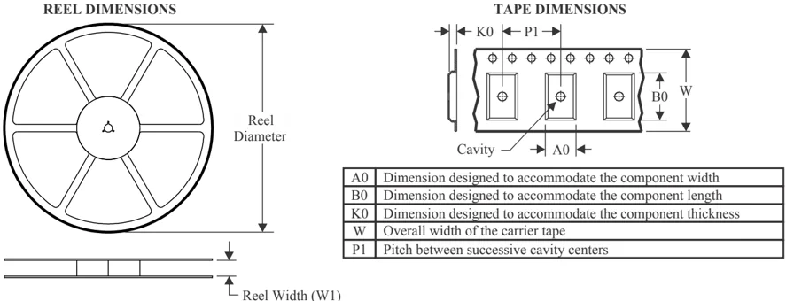
TAPE DIMENSIONS
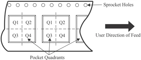
| A0 | Dimension designed to accommodate the component width |
|---|---|
| B0 | Dimension designed to accommodate the component length |
| K0 | Dimension designed to accommodate the component thickness |
| W | Overall width of the carrier tape |
| P1 | Pitch between successive cavity centers |
QUADRANT ASSIGNMENTS FOR PIN 1 ORIENTATION IN TAPE
*All dimensions are nominal
| Device | Package Type | Package Drawing | Pins | SPQ | Reel Diameter (mm) | Reel Width W1 (mm) | A0 (mm) | B0 (mm) | K0 (mm) | P1 (mm) | W (mm) | Pin1 Quadrant |
|---|---|---|---|---|---|---|---|---|---|---|---|---|
| MAX232DR | SOIC | D | 16 | 2500 | 330.0 | 16.4 | 6.5 | 10.3 | 2.1 | 8.0 | 16.0 | Q1 |
| MAX232DR | SOIC | D | 16 | 2500 | 330.0 | 16.4 | 6.5 | 10.3 | 2.1 | 8.0 | 16.0 | Q1 |
| MAX232IDR | SOIC | D | 16 | 2500 | 330.0 | 16.4 | 6.5 | 10.3 | 2.1 | 8.0 | 16.0 | Q1 |
| MAX232IDR | SOIC | D | 16 | 2500 | 330.0 | 16.4 | 6.5 | 10.3 | 2.1 | 8.0 | 16.0 | Q1 |
| MAX232IDWR | SOIC | DW | 16 | 2000 | 330.0 | 16.4 | 10.75 | 10.7 | 2.7 | 12.0 | 16.0 | Q1 |
| MAX232NSR | SOP | NS | 16 | 2000 | 330.0 | 16.4 | 8.1 | 10.4 | 2.5 | 12.0 | 16.0 | Q1 |
Pack Materials-Page 1
PACKAGE MATERIALS INFORMATION
10-Aug-2026
TAPE AND REEL BOX DIMENSIONS
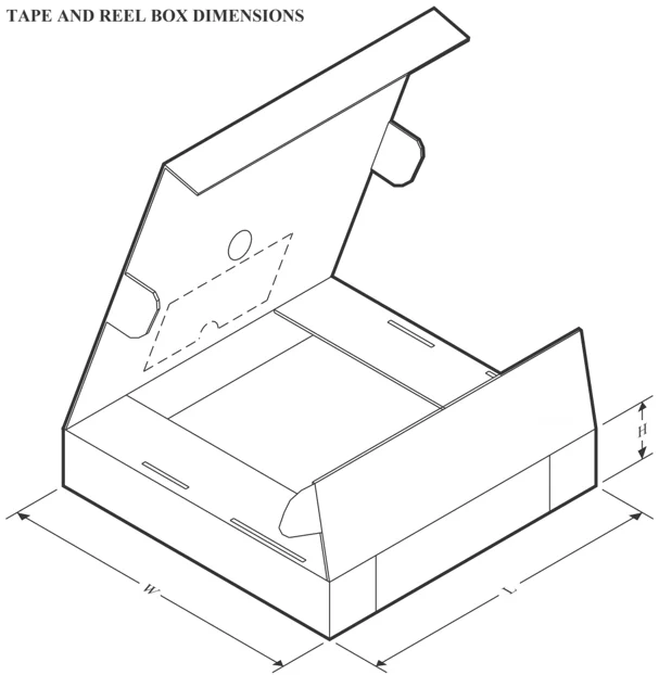
*All dimensions are nominal
| Device | Package Type | Package Drawing | Pins | SPQ | Length (mm) | Width (mm) | Height (mm) |
|---|---|---|---|---|---|---|---|
| MAX232DR | SOIC | D | 16 | 2500 | 340.5 | 336.1 | 32.0 |
| MAX232DR | SOIC | D | 16 | 2500 | 333.2 | 345.9 | 28.6 |
| MAX232IDR | SOIC | D | 16 | 2500 | 340.5 | 336.1 | 32.0 |
| MAX232IDR | SOIC | D | 16 | 2500 | 353.0 | 353.0 | 32.0 |
| MAX232IDWR | SOIC | DW | 16 | 2000 | 350.0 | 350.0 | 43.0 |
| MAX232NSR | SOP | NS | 16 | 2000 | 353.0 | 353.0 | 32.0 |
Pack Materials-Page 2
PACKAGE MATERIALS INFORMATION
10-Aug-2026
TUBE
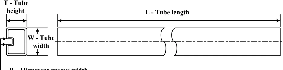
*All dimensions are nominal
| Device | Package Name | Package Type | Pins | SPQ | L (mm) | W (mm) | T (μm) | B (mm) |
|---|---|---|---|---|---|---|---|---|
| MAX232N | N | PDIP | 16 | 25 | 506 | 13.97 | 11230 | 4.32 |
| MAX232N.A | N | PDIP | 16 | 25 | 506 | 13.97 | 11230 | 4.32 |
| MAX232N.B | N | PDIP | 16 | 25 | 506 | 13.97 | 11230 | 4.32 |
| MAX232NE4 | N | PDIP | 16 | 25 | 506 | 13.97 | 11230 | 4.32 |
Pack Materials-Page 3
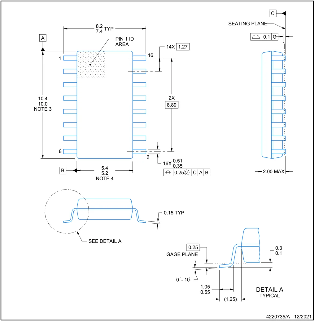
PACKAGE OUTLINE
NS0016A
SOP - 2.00 mm max height
SOP
4220735/A 12/2021
NOTES:
- All linear dimensions are in millimeters. Dimensions in parenthesis are for reference only. Dimensioning and tolerancing per ASME Y14.5M.
- This drawing is subject to change without notice.
- This dimension does not include mold flash, protrusions, or gate burrs. Mold flash, protrusions, or gate burrs shall not exceed 0.15 mm, per side.
- This dimension does not include interlead flash. Interlead flash shall not exceed 0.25 mm, per side.

EXAMPLE BOARD LAYOUT
NS0016A
SOP - 2.00 mm max height
SOP
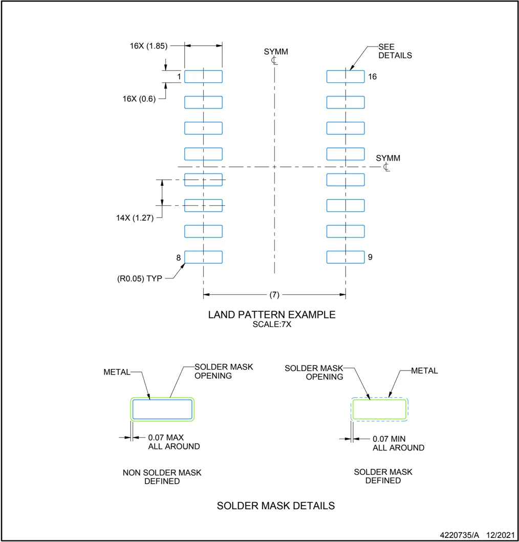
16X (1.85) SYMM SEE DETAILS 1 16 16X (0.6) SYMM 14X (1.27) 8 9 (R0.05) TYP (7) LAND PATTERN EXAMPLE SCALE:7X
METAL SOLDER MASK OPENING 0.07 MAX ALL AROUND NON SOLDER MASK DEFINED
SOLDER MASK OPENING METAL 0.07 MIN ALL AROUND SOLDER MASK DEFINED
SOLDER MASK DETAILS
4220735/A 12/2021
NOTES: (continued) 5. Publication IPC-7351 may have alternate designs. 6. Solder mask tolerances between and around signal pads can vary based on board fabrication site.

EXAMPLE STENCIL DESIGN
NS0016A
SOP - 2.00 mm max height
SOP
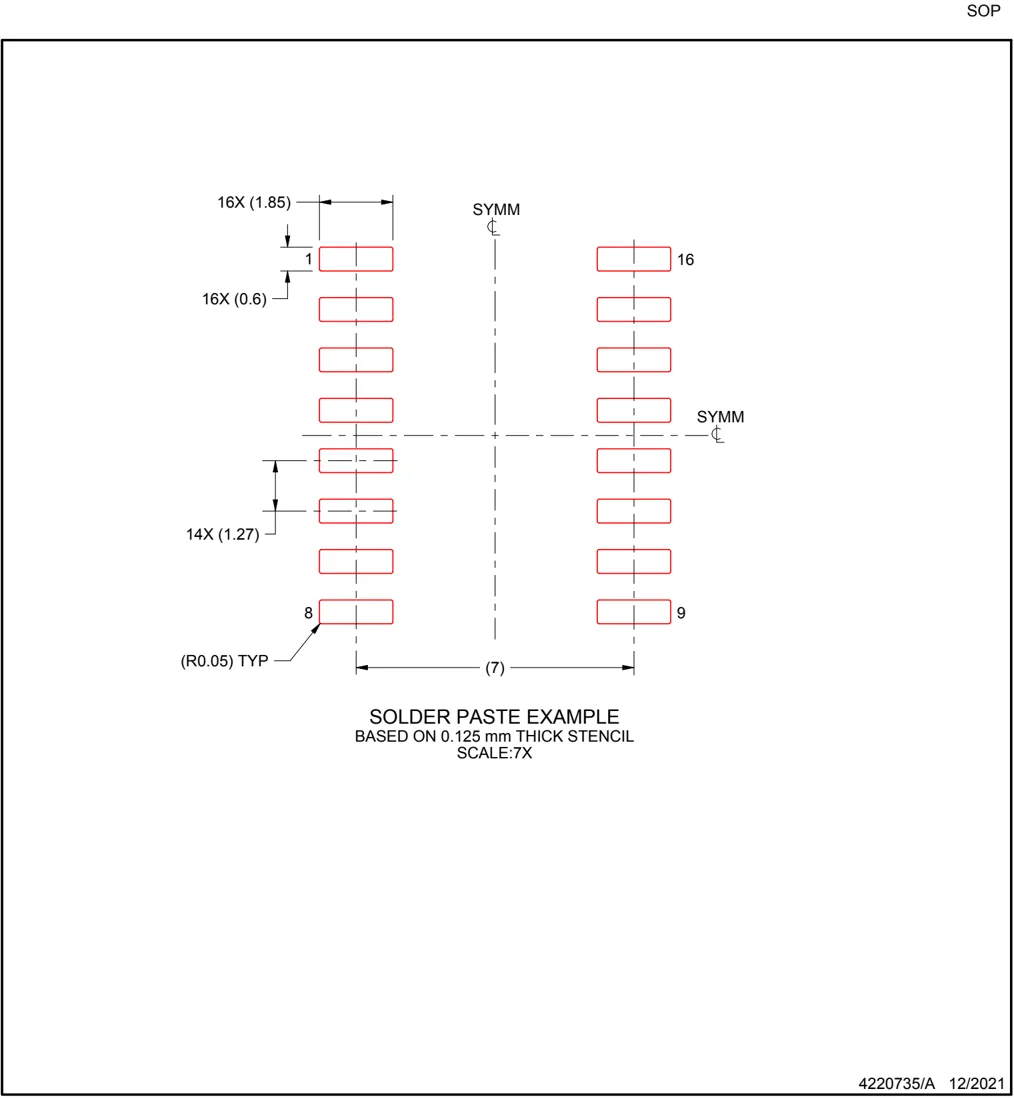
16X (1.85) SYMM 1 16 16X (0.6) SYMM 14X (1.27) 8 9 (R0.05) TYP (7)
SOLDER PASTE EXAMPLE BASED ON 0,125 mm THICK STENCIL SCALE:7X
4220735/A 12/2021
NOTES: (continued)
- Laser cutting apertures with trapezoidal walls and rounded corners may offer better paste release. IPC-7525 may have alternate design recommendations.
- Board assembly site may have different recommendations for stencil design.

MECHANICAL DATA
D (R-PDSO-G16) PLASTIC SMALL OUTLINE
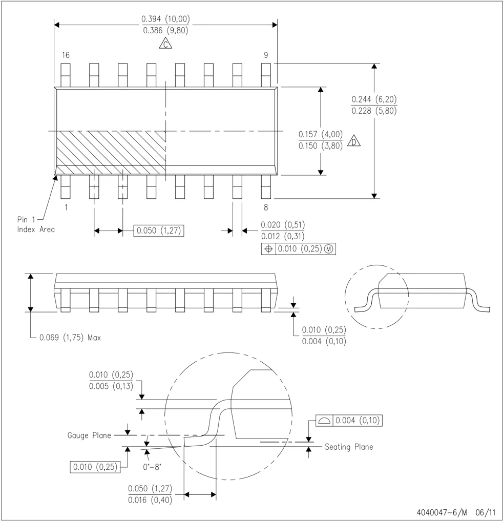
4040047-6/M 06/11
NOTES: A. All linear dimensions are in inches (millimeters). B. This drawing is subject to change without notice. C. Body length does not include mold flash, protrusions, or gate burrs. Mold flash, protrusions, or gate burrs shall not exceed 0.006 (0,15) each side. D. Body width does not include interlead flash. Interlead flash shall not exceed 0.017 (0,43) each side. E. Reference JEDEC MS-012 variation AC.

GENERIC PACKAGE VIEW
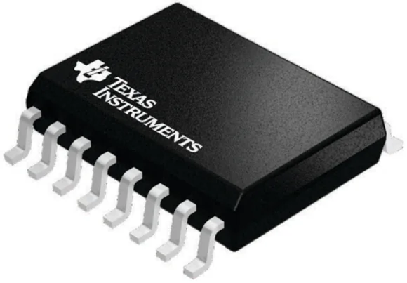
DW 16 7.5 x 10.3, 1.27 mm pitch
SOIC - 2.65 mm max height SMALL OUTLINE INTEGRATED CIRCUIT
This image is a representation of the package family, actual package may vary. Refer to the product data sheet for package details.
4224780/A

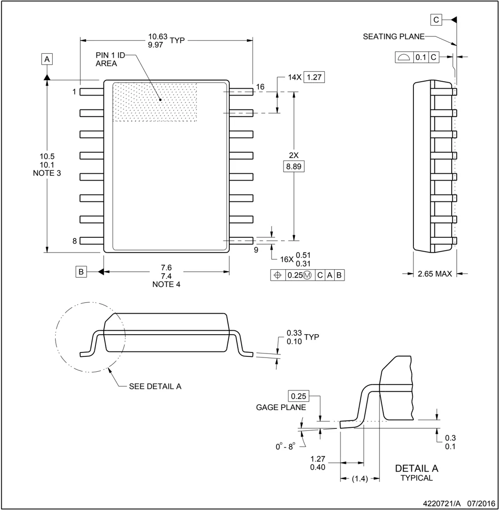
DW0016A
PACKAGE OUTLINE
SOIC - 2.65 mm max height
SOIC
NOTES:
- All linear dimensions are in millimeters. Dimensions in parenthesis are for reference only. Dimensioning and tolerancing per ASME Y14.5M.
- This drawing is subject to change without notice.
- This dimension does not include mold flash, protrusions, or gate burrs. Mold flash, protrusions, or gate burrs shall not exceed 0.15 mm, per side.
- This dimension does not include interlead flash. Interlead flash shall not exceed 0.25 mm, per side.
- Reference JEDEC registration MS-013.

EXAMPLE BOARD LAYOUT
DW0016A SOIC - 2.65 mm max height
SOIC
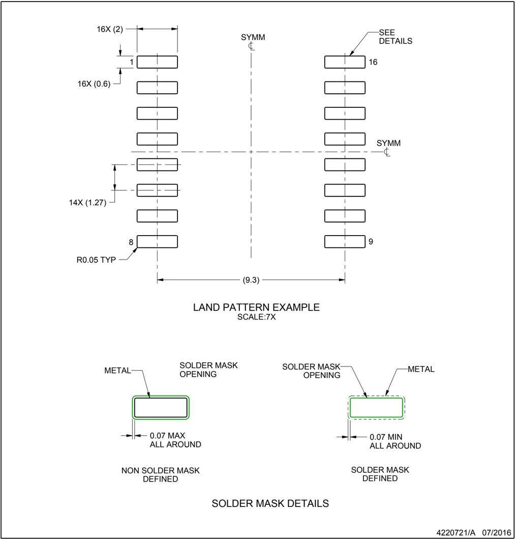
4220721/A 07/2016
NOTES: (continued)
- Publication IPC-7351 may have alternate designs.
- Solder mask tolerances between and around signal pads can vary based on board fabrication site.

EXAMPLE STENCIL DESIGN
DW0016A SOIC - 2.65 mm max height SOIC
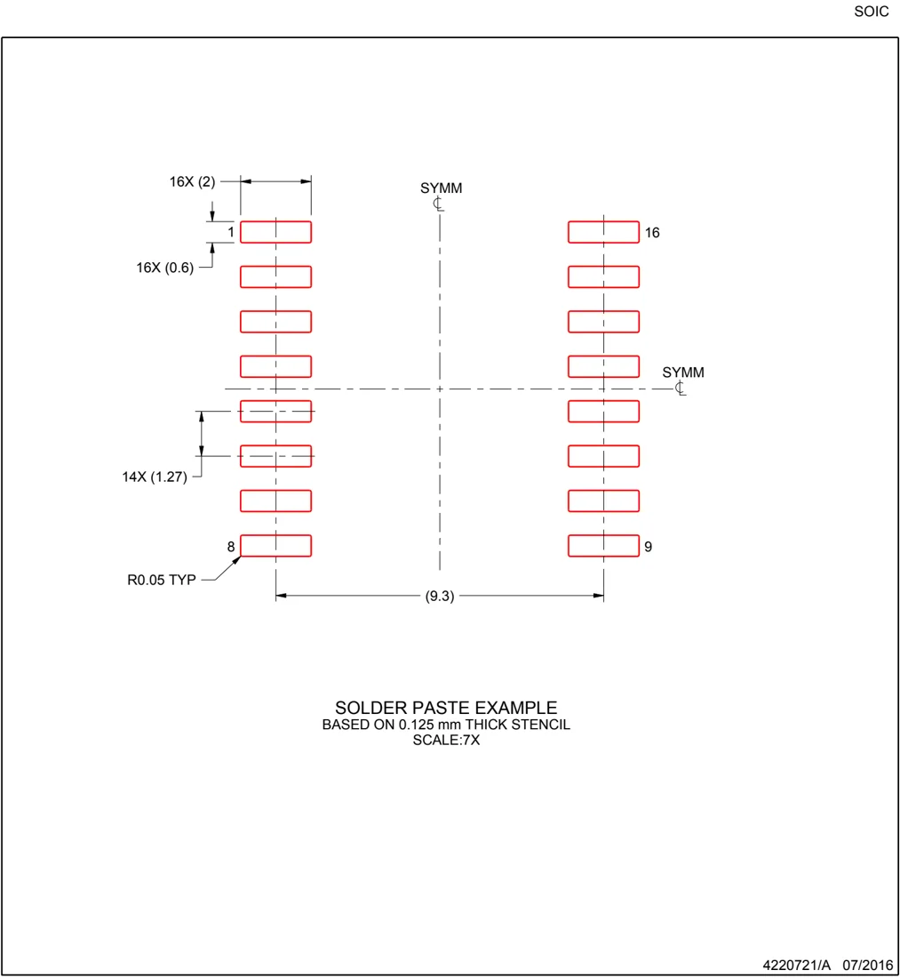
SOLDER PASTE EXAMPLE BASED ON 0.125 mm THICK STENCIL SCALE:7X
4220721/A 07/2016
NOTES: (continued)
- Laser cutting apertures with trapezoidal walls and rounded corners may offer better paste release. IPC-7525 may have alternate design recommendations.
- Board assembly site may have different recommendations for stencil design.

MECHANICAL DATA
N (R-PDIP-T**)
16 PINS SHOWN
PLASTIC DUAL-IN-LINE PACKAGE
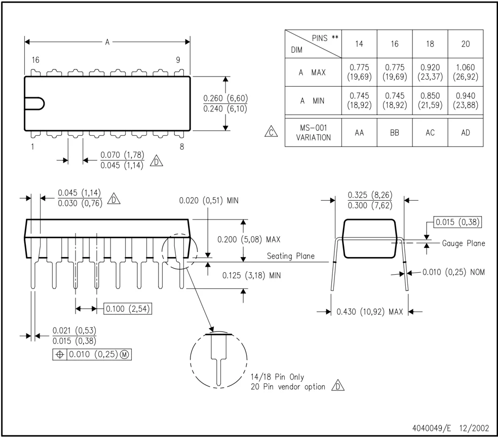
NOTES: A. All linear dimensions are in inches (millimeters). B. This drawing is subject to change without notice. △C Falls within JEDEC MS-001, except 18 and 20 pin minimum body length (Dim A). △D The 20 pin end lead shoulder width is a vendor option, either half or full width.
4040049/E 12/2002

IMPORTANT NOTICE AND DISCLAIMER
TI PROVIDES TECHNICAL AND RELIABILITY DATA (INCLUDING DATASHEETS), DESIGN RESOURCES (INCLUDING REFERENCE DESIGNS), APPLICATION OR OTHER DESIGN ADVICE, WEB TOOLS, SAFETY INFORMATION, AND OTHER RESOURCES “AS IS” AND WITH ALL FAULTS, AND DISCLAIMS ALL WARRANTIES, EXPRESS AND IMPLIED, INCLUDING WITHOUT LIMITATION ANY IMPLIED WARRANTIES OF MERCHANTABILITY, FITNESS FOR A PARTICULAR PURPOSE OR NON-INFRINGEMENT OF THIRD PARTY INTELLECTUAL PROPERTY RIGHTS.
These resources are intended for skilled developers designing with TI products. You are solely responsible for (1) selecting the appropriate TI products for your application, (2) designing, validating and testing your application, and (3) ensuring your application meets applicable standards, and any other safety, security, regulatory or other requirements.
These resources are subject to change without notice. TI grants you permission to use these resources only for development of an application that uses the TI products described in the resource. Other reproduction and display of these resources is prohibited. No license is granted to any other TI intellectual property right or to any third party intellectual property right. TI disclaims responsibility for, and you fully indemnify TI and its representatives against any claims, damages, costs, losses, and liabilities arising out of your use of these resources.
TI’s products are provided subject to TI’s Terms of Sale, TI’s General Quality Guidelines, or other applicable terms available either on ti.com or provided in conjunction with such TI products. TI’s provision of these resources does not expand or otherwise alter TI’s applicable warranties or warranty disclaimers for TI products. Unless TI explicitly designates a product as custom or customer-specified, TI products are standard, catalog, general purpose devices.
TI objects to and rejects any additional or different terms you may propose.
Copyright © 2026, Texas Instruments Incorporated
Last updated 10/2025